
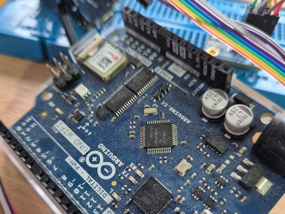
The usual interrupt timer libraries and examples may not work on the Arduino UNO WiFi Rev2 and Nano Every because they use the ATmega4809 processor. So here is a quick and simple example showing how to use one of the inbuilt timers (TCB0) to toggle a variable that can be checked in the loop routine.
For many applications, this is the best way to execute code at regular time intervals. The alternative, using delay(millis) within the loop routine, doesn’t allow your code to poll peripherals and react quickly to things like serial input or receipt of a radio or WiFi message.
All testing was done on a UNO WiFi Rev2.
Timers available on the ATmega4809
The 4809 processor has one A timer (TCA) and four B timers (TCB). TCA is a 16 bit counter, but can be split into two 8 bit counters if needed (split mode) which are referred to as the “low byte timer” and the “high byte timer”. The main clock for the CPU runs at 16 MHz. The A timer (TCA) has a default pre-scaled clock (main CPU clock divided by 64) which is used by some of the Arduino core libraries to do things like playing tones (using TCB1) or counting time since start with functions like millis() and micros() (using TCB3). So you need to be a bit careful about choosing the clock settings and the timers themselves as you wouldn’t want to mess up core functionality.
The code shown here uses timer TCB0 because other libraries tend not to use it. I show two options for clock source:
- The TCA clock. This clock is already pre-scaled by a factor of 64, giving 250 kHz. It’s okay to use it for TCB0, but best not to change the pre-scaler.
- The main clock. It’s best to set a pre-scaler and my example code shows this set to divide the frequency by 2, giving 8MHz on a UNO WiFi Rev2.
Sketch Code
The sketch shown here doesn’t do anything very useful, but it does provide an easy-to-use basis for practical and useful code using hardware interrupt timers. Basically, it uses TCB0 to call an Interrupt Service Routine (ISR) many times a second. The ISR increments a counter which is used to assign 1 to a global variable once per second. The main loop routine of the sketch is multi-tasking (kind of) in so far as it waits for serial input at the same time as toggling the built-in LED once a second and writing values to the serial monitor every ten seconds without any one activity really blocking any other – or inducing sluggish response times.
I wrote this code a while ago and, if my memory serves me correctly, it is partially original work. However, it draws from several online examples written by others which I will try to fully reference at the end (hoping not to miss any).
Initialisation function
The following function is used to initialise the timer. Depending on the value of “USE_TCA_CLOCK”, it sets up TCB0 to use one of the two clock sources mentioned above. It also configures TCB0 to trigger an interrupt whenever it has counted up to 25000.
The code makes use of a global variable called toggle1. This has to be declared in the main ino file before the setup routine and it must use the “volatile” keyword to show that its value can change outside the normal scope. [To purists, the use of global variables may not look like the best way to write C code, but pragmatism is needed and variables with global scope are well suited to interrupt-driven applications].
void configureTCB0asTimer() {
  // Configure hardware timer, TCB0, to repeatedly call an Interrupt Service Routine

  cli();  // stop interrupts
  /* -----------------------------  Initialise TCB0  ------------------------------ */
  // Set the mode of operation for timer/counter TCB0 to 'periodic interrupt'
  TCB0_CTRLB = TCB_CNTMODE_INT_gc;
  // Set the TOP value - the COMPARE count that will trigger an interrupt
  TCB0_CCMP = 25000;
  // Enable the interrupt
  TCB0.INTCTRL = TCB_CAPT_bm;
#if USE_TCA_CLOCK == 1
  // Enable the timer/counter with TCA clock as source
  TCB0_CTRLA = TCB_CLKSEL_CLKTCA_gc | TCB_ENABLE_bm;
#else
  // Enable the timer/counter with main clock as source and DIV2 speed reduction
  TCB0_CTRLA = TCB_CLKSEL_CLKDIV2_gc | TCB_ENABLE_bm;
#endif
  /* ------------------------------------------------------------------------------ */
  sei();  // restart interrupts

  // Initialise the Timer Interrupt counter
  toggle1 = 0;
}
The Interrupt Service Routine
Here is the code for the interrupt service routine that is called whenever the TCB0 counter reaches 25000. It increments the variable icount and uses a fixed divisor of either 10 or 320, depending which clock source is being used. This means that toggle1 is set once per second. The code shown here should offer quite good precision interval timing, but I haven’t thoroughly checked this aspect of it.
If you want different intervals, just change the divisor. The maths is very simple, but please note icount is reset to zero when it reaches 32000. Only choose values for the divisor where the quotient is an integer (i.e. 32000 divided by your chosen number must be a whole number) because otherwise there will be occasional glitches in the time interval between each value toggle event. If you need very short sub-second intervals, it may be best to use the main clock divided by 2 rather than the TCA clock.
Once again, it makes use of a global variable, icount, which has to be declared in the main ino file before the setup routine.
You will need to copy this code and the code above for the function configureTCB0asTimer() into your ino file.
ISR(TCB0_INT_vect){
  //timer TCB interrupt handler

#if USE_TCA_CLOCK == 1
  if ((icount % 10) == 0) {
#else
  if ((icount % 320) == 0) {
#endif
    // This should be true once per second
    toggle1 = 1;
    if (icount > 32000) icount = 0;
  }
  icount++;

  // clear the interrupt flag
  TCB0.INTFLAGS = TCB_CAPT_bm;
}
The Sketch
Now we can look at the main code of the sketch, shown here complete with everything except the two functions described and listed above.
//For Arduino UNO WiFi Rev2, Nano Every - boards with ATMEL ATMEGA 4809
//This code enables timer TCB0:
// The interrupt service routine may be called 320 times per second using the main
// clock as source (Div 2) or 10 times a second using the TCA clock running at 250kHz.
// Set this #define to either 0 or 1 to choose your clock source
#define USE_TCA_CLOCK 0
//storage variables
volatile long int icount = 0;
volatile boolean toggle1 = 0;
void setup(){
Serial.begin(9600);
while (!Serial); //waits for serial terminal to be open
delay(4001);
#if USE_TCA_CLOCK == 1
Serial.print("Timer TCB0 demo using the TCA clock");
#else
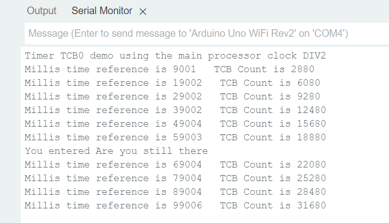
Serial.print("Timer TCB0 demo using the main processor clock DIV2");
#endif
Serial.println();
//set the built-in LED pin as an output
pinMode(LED_BUILTIN, OUTPUT);
configureTCB0asTimer();
}
void loop() {
static int tenSecCount = 0;
static bool ledState = false;
static char sendbuffer[48];
static int sendlength = 0;
// Check for input from the Serial Console
if (Serial.available() > 0) {
// Get next char from serial console input
char input = Serial.read();
if ((input == '\r') && (sendlength > 0)) {
// A line of text has been entered
sendbuffer[sendlength] = '\0';
sendlength = 0;
Serial.print("You entered ");
Serial.println(sendbuffer);
} else if (input != '\r' && sendlength < 47) {
sendbuffer[sendlength] = input;
sendlength++;
}
// Check if the interrupt timer interval toggle has been triggered
} else if (toggle1) {
// Another second has passed. Immediately reset the toggle variable
toggle1 = 0;
tenSecCount++;
if (tenSecCount > 9) {
Serial.print("Millis time reference is ");
Serial.print(millis() - 4000);
Serial.print(" TCB Count is ");
Serial.print(icount - 1);
Serial.println();
tenSecCount = 0;
}
// Make the built-in LED flash on/off every second
digitalWrite(LED_BUILTIN, ledState ? HIGH : LOW);
ledState = !ledState;
}
delay(1);
}
You should see something like this in the Serial Monitor:
The line of code at the end, delay(1), is not strictly necessary and could even create problems if you want to do very accurate timing of very short intervals. I included it only because I feel uneasy about loops that run at full speed doing stuff. That is probably illogical, but then nobody’s perfect. Hope this article was useful.
References
Getting started with TCB (microchip.com)
Getting Started with TCA (microchip.com)
http://ww1.microchip.com/downloads/en/DeviceDoc/megaAVR-0-series-Family-Data-Sheet-40002015C.pdf
Arduino Nano Every Timers and PWM – Kevin’s Blog (wordpress.com)
http://ww1.microchip.com/downloads/en/DeviceDoc/megaAVR0-series-Family-Data-Sheet-DS40002015B.pdf 34
Timer/Counter Woes – Tom Almy’s Blog
Atmega4808/4809 Input capture example – Nano Family / Nano Every – Arduino Forum
Leave a Reply