I had a fairly simple objective – to build a battery powered outdoor weather station using an Arduino. The very first step, choosing which Arduino board to use, proved to be more complex than I expected. In fact, the array of parameters in my selection matrix kept growing over time as my knowledge increased during the design and build process.
High on my list of needs was that the weather station should be able to run on battery power, maybe with a solar panel, and it must run unattended for at least a month; preferably two or more. Basically, I just didn’t want to be changing the battery every few days or getting gaps in my recorded data. I started by looking at board choice and ways to minimise power demand in the Arduino, then gradually moved on by considering battery options and finally using a solar panel to keep the battery charged.
Here, I review the criteria and parameters that were most relevant to my choice of Arduino microcontroller board. A companion article here describes what I found when testing options for low power and prolonged battery life, once the board was chosen.
Project requirements and selection criteria
The basic functional specification for the design was as follows:
- Battery powered, possibly supplemented with a solar panel
- Various sensors (using I2C or SPI) would be used to get readings at about 10 minute intervals
- Readings to be transmitted by radio to a base station – I wanted long range with no presumption of access to Wi-Fi
- Low maintenance – not requiring frequent visits to change batteries or download data
- Not too expensive, but I was prepared to buy and try several different devices in order to reach the best solution
Radio module
After experimenting with a couple of different radio modules, the RFM69HCW operating at 868MHz was my preferred solution. It seemed to be fairly robust and reliable, with a decent range that wasn’t horribly depleted by passing through masonry walls. The self-contained modules made by Adafruit were attractive because they included a voltage regulator and logic signal level buffering that allowed operation with 3.3V or 5V. They connect using the SPI bus.
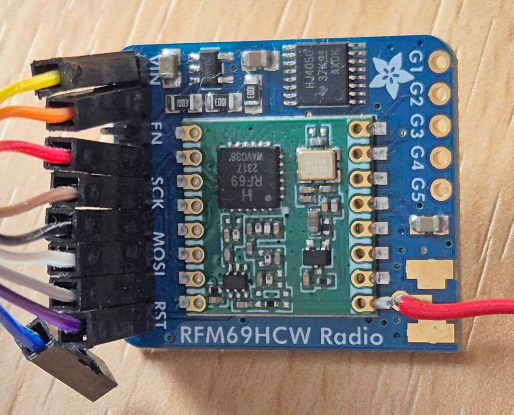
Another possibility was the Adafruit Feather with built-in RFM69HCW module which is available with the RP2040 processor or the SAMD21 M0 processor. Price and availability drove me towards the RP2040 version.

Power options – the VIN pin
When considering battery connection, I wanted flexibility so I could test different strategies. Ideally, this meant finding a board with a VIN pin and voltage regulator allowing it to be powered using a wide range of input voltages. The Adafruit Feather RP2040 RFM was rather weak in this respect, but it did include a battery connector and battery management chip. Considering the radio module was integrated and the price very reasonable, it definitely deserved consideration.
Other power options to consider
While on the topic of battery power and board power options, It’s also worth mentioning the limitations that can arise when you need to provide power to a peripheral device such as a sensor or radio module. When using the onboard regulator – as would be needed when directly connecting batteries – you really want to be able to take a feed from the board’s regulated voltage rail to power the peripherals. This is typically 3.3V or 5V and most Arduino boards provide a pin for this purpose. It is really important to check how much current can be drawn from this pin. Some peripherals require quite a lot of power – radio modules do, especially when transmitting.
To get around this limitation, you may choose to connect the batteries to your own voltage regulator (or use a battery management module) and bypass the onboard voltage regulator on the Arduino. However, some boards don’t make provision for connection of a regulated supply at the voltage used for directly powering the components on the board. The Arduino Nano 33 BLE does allow this, but you have to cut a small track on the board and this allows the 3.3V pin (normally a power output pin) to be re-purposed as a power input pin.

Processor type and library compatibility
When I first started experimenting with Arduinos, I failed to appreciate the significance of the microprocessor model and focussed instead on value for money and inclusion of built-in peripherals such as sensors and radio chips. However, it soon became apparent that some of the software libraries only work with certain processor architectures. This is because the functionality provided by some libraries relies on specific hardware features. These features vary widely from one model of processor to another – both in terms of whether the hardware supports it at all, but also in terms of the registers available and how they are programmed. This turned out to be the case for the low power libraries that I planned to use to extend battery life and the OneWire library required when using some low cost temperature sensors. It also applies to some libraries that leverage hardware timers to trigger interrupt service routines for tasks such as getting sensor readings every 60 seconds.
After doing some research online alongside bench tests for operation in low power mode, it looked like the deepSleep function in Arduino’s low power library offered the simplest and most effective solution for pausing between sensor readings. The RTCZero low power library is also worth considering if you want fine granularity in the settings, but it is more complicated to use. The documentation for the RTCZero library states that it is only compatible with boards using the SAMD21 processor and this is what I found in practice. Arduino’s low power library doesn’t work with the RP2040 processor.
I tried various different sensors including the DS18B20 which is available in different packages including sealed temperature probes on the end of quite long cables. These could be useful for simultaneously monitoring a number of temperatures such as at different heights on a hot water tank. They are fairly inexpensive and, with care, can be made to work over quite long cable lengths. However, they require the OneWire library – a library that is not compatible with all processors.
The eventual matrix of criteria
This list summarises the criteria I looked at to select a board:
- The basic power demand of each microcontroller board
- Processor type and compatibility with certain libraries I wanted to use
- Flexibility of external power options, especially using the VIN pin
- Ability to power peripherals, especially sensors using the I2C bus and a RFM69HCW radio module
- Usefulness of integrated features and capabilities
- Total cost, taking into account the cost of required peripheral modules
Starting at the beginning of the list, it is pretty easy to to find online information comparing the power demand of various Arduino boards. For example, this article:
How Long Can An Arduino Run On Batteries? I Tested 6 Of The Most Common Boards
Armed with this basic information, it looked like the 3.3V Nano boards were favourites. This allowed me to produce a shortlist.
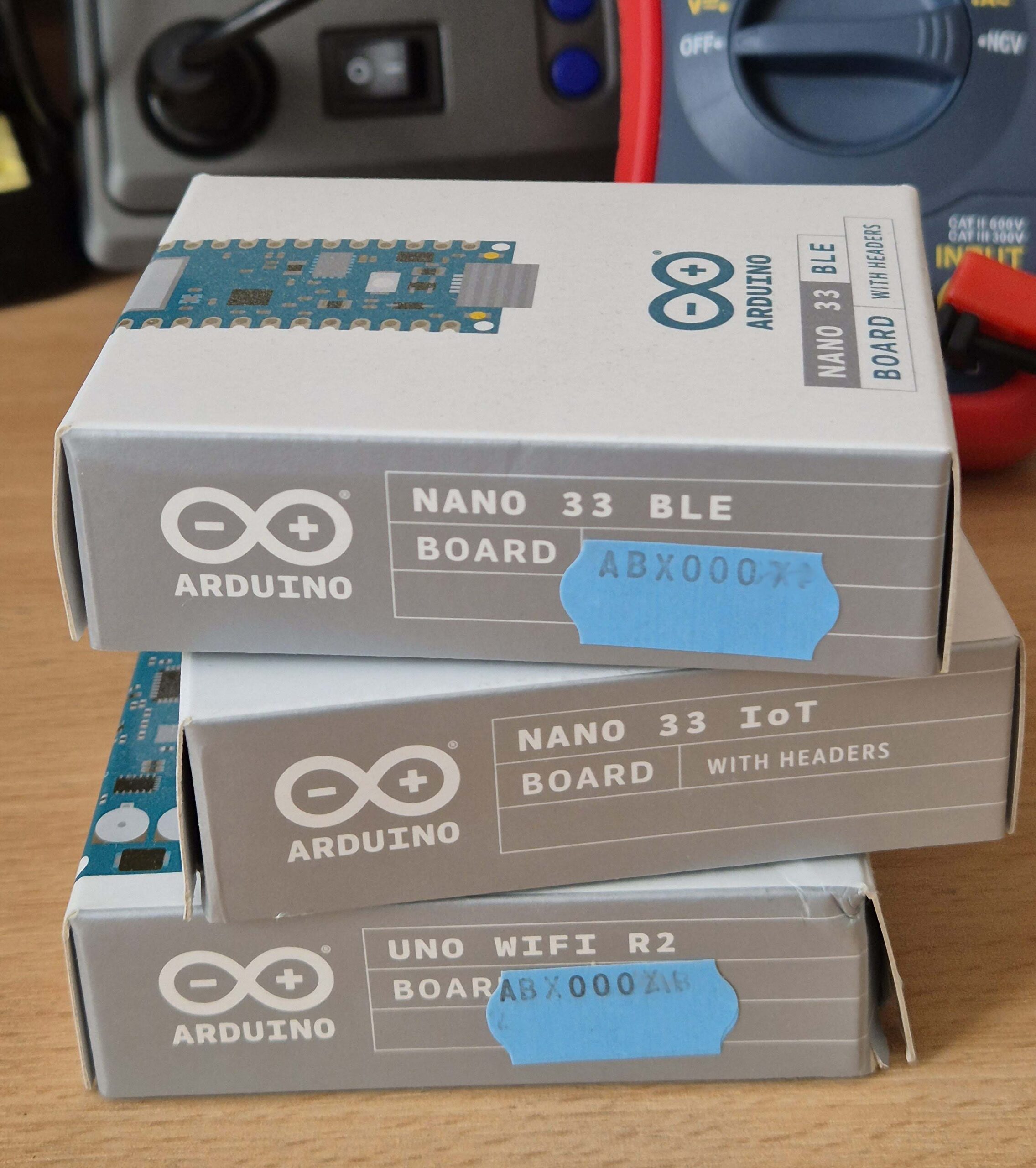
My shortlist
In addition to the two Nano 33 boards, I added the Adafruit Feather RP2040 RFM simply because it included the radio module I wanted, it was very compact and was relatively cheap. The last two on this list were not actually tested, but should certainly be considered. The M0 version of the Feather was out of stock when I was buying and also cost quite a lot more than the RP2040 version. I didn’t buy a sample of the Arduino MKR WiFi 1010 board because it offered no price advantage over the Nano 33 IoT and had a more limited voltage range on the VIN pin.
- Nano 33 BLE
- Nano 33 IoT
- Adafruit Feather RP2040 RFM69HCW
- Adafruit Feather M0 RFM69HCW (not tested)
- Arduino MKR WiFi 1010 (not tested)
| Model of Arduino Board | Processor | Compatibility with libraries | VIN voltage range | Allows you to power directly from a 3.3V supply | Has onboard Battery Management Chip (BMS) | Can deliver enough power for peripherals such as RFM69 | Other bonus onboard goodies |
| Nano 33 BLE | 64MHz nRF52840 Nordic Semiconductors | LowPower Yes RTCZero No OneWire No | 4.5V to 18V | Yes, cut track first | No | No *See notes | NINA B306 supports BLE 9-axis IMU |
| Nano 33 IoT | 48MHz ARM Cortex-M0 32-bit SAMD21 | LowPower Yes RTCZero Yes OneWire Yes | 4.5V to 18V | Officially? No. Unofficially? *See notes | No | Yes | NINA W102 supports Wi-Fi or BLE 6-axis IMU |
| Feather RP2040 RFM69 | 125MHz RP2040 Pico (dual core) | No low power lib *See notes OneWire Yes | No VIN pin | Not recommended | Yes | Yes (integral) | RFM69HCW 8MB SPI Flash Stemma-QT I2C |
Comparison summary
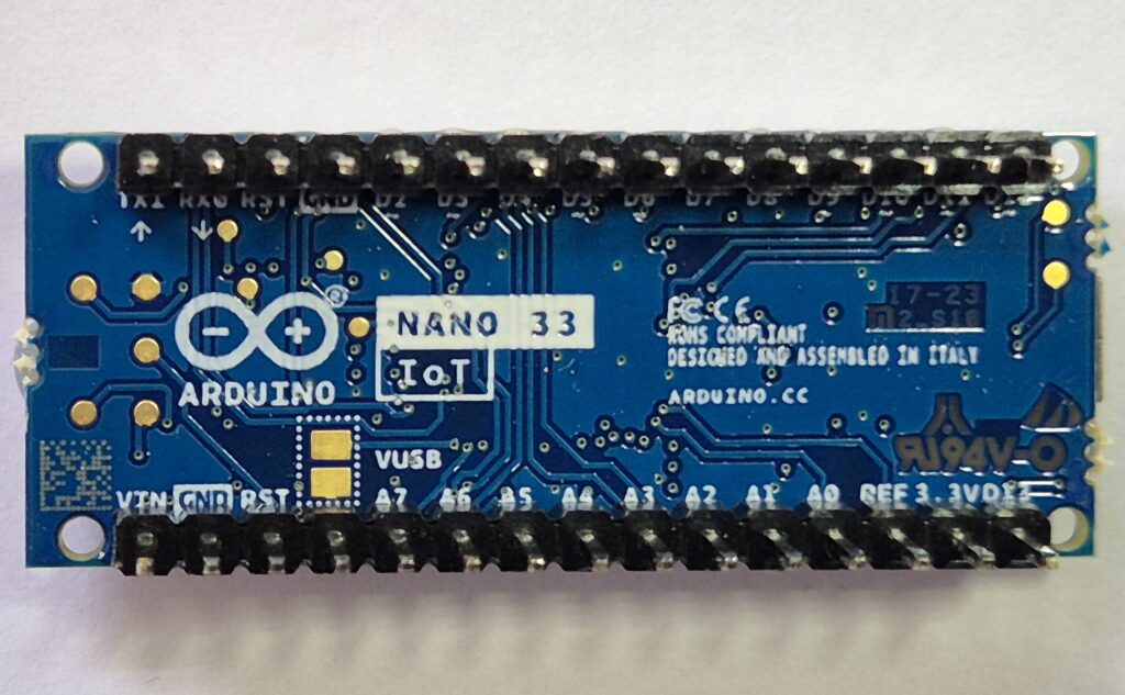
Nano 33 IoT
It is compatible with all the libraries I wanted to use and mostly has the flexible power options I wanted. For example, its integral voltage regulator can deliver enough power on the 3.3V pin to drive the RFM69HCW. Powering it from an external 3.3V supply may be possible, but this is risky because they don’t provide a track you can cut to isolate the 3.3V pin from the regulator output. Having the integral Wi-Fi radio chip and an IMU is quite a bonus, but only if you need them of course.
The Nano 33 IoT lacks the integral battery management of the Feather, but in some respects this is an advantage because, ultimately, it allows you a greater choice regarding battery types and battery combinations. Operating with external power sources, including add-on battery management circuits that support solar panels, is discussed in more detail in another article (coming soon).
Nano 33 BLE
The Nano 33 BLE has a VIN pin and allows a good range of options for external power. It is inherently a low power board so would be a good choice for prolonged battery life. On the negative side, it has very limited power delivery (about 50mA maximum) for peripherals connected to its 3.3V pin. As the RFM69HCW needs more than 50mA when transmitting, this was a major drawback. This is mitigated by the fact that you can connect an external 3.3V supply to the 3.3V pin and easily isolate it from the output of the onboard voltage regulator. However, it is not compatible with some of the libraries I want to use because of the processor chip it uses. In particular, I couldn’t get it to work with temperature sensors that use the DS18B20 chip. The final nail in its coffin came when I found that Bluetooth Low Energy (BLE) wasn’t really suitable for transmitting data readings in my applications – for remote monitoring application like my weather station, it lacks range or wall penetration; for fast streaming of rapidly sampled data, such as from an IMU, I just couldn’t figure out how to make it send the data fast enough.
Adafruit Feather with integral RFM69HCW radio
Putting the RP2040 Feather board into a low power mode between sensor readings is possible, but is a bit messy. I did it by calling functions to shut down various onboard peripherals and slowing the system clock by calling the set_sys_clock_khz() function, but I wasn’t able to directly measure the impact on current demand. The SAMD21 M0 version of the Feather would be easier to put into low power sleep mode, but it costs quite a lot more than the RP2040. The Feathers have somewhat different external power options – on the plus side, they include a battery connector (Li-Poly or Li-Ion, 3.7V) and an integral battery management chip to manage the charging of the battery. However, on the negative side, they don’t have a VIN pin so the only external power option available is the USB port. This means any external power source must be regulated to 5V and presented as a USB connector before it can be used. The documentation strongly advises against connecting a power source directly to the 3.3V pin so I didn’t try it.
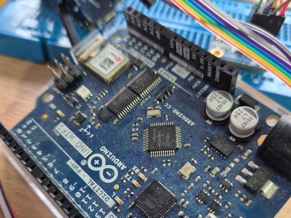
MKR WiFi 1010
The Arduino MKR WiFi 1010 board wasn’t tested, but as it uses a SAMD21 processor it would be compatible with the RTCZero and OneWire libraries. While there are alternative MKR boards – including one that doesn’t have a Wi-Fi chip – they were either more expensive or availability was a problem. I understand the expensive ones have a superior real time clock and possibly other components are higher spec too. I may still try this one day in the future, but I ruled it out in this round of tests especially as it has a more limited voltage range on the VIN pin and was quite expensive.
Conclusion: My choice? The Nano 33 IoT
I may still change my mind, but my current favourite is the Nano 33 IoT. This is mainly because it is compatible with all the libraries I wanted to use and it has the flexible power options I wanted. It is very disappointing that you can’t cut a track to isolate the 3.3V pin from the regulator output as is done on the BLE board. However, I have so far had no problems despite this omission
There is a companion article that explains a lot more about the testing I did after choosing the Nano 33 IoT as my preferred starting point. It includes results from testing with different low power strategies and different battery combinations:
Nano 33 IoT: Testing battery options and low power mode – Smartvox Labs
Another article is under construction in which I look at how things went when a small solar panel was introduced into the mix.
Leave a Reply