
Summary
NRF24L01 modules, because of their low cost, are an appealing option for data transmission over modest distances. They are best suited to unobstructed “line-of-sight” transmission, but one might hope at least to reach an adjacent room indoors. Here, I describe my experience testing a pair of NRF24L01 modules, each linked to an Arduino Nano 33 BLE. My first attempt was a complete failure and I then had to figure out how to debug it. I didn’t even know if the transmitter or the receiver was the cause of the problem. Or even both! I will explain how I tested it and include code samples.
This article looks mainly at power options for the radio module and the approach used for testing and debugging. At the end I summarise the results and offer my conclusions. But here’s a spoiler – I eventually to decide to look for a better alternative to use in my project. Hopefully, this article will help others who may be struggling to get these modules working or to decide if they are the right solution.
The project brief
The intended application was a project to measure temperatures throughout a very large house. There would one device per room, each based around an Arduino processor board. These peripheral nodes would be connected, by cables, to one or more temperature and humidity sensors. Each node would use a radio module to send the sensor data back to a central hub for collection and storage. I wanted to use the Arduino Nano 33 as the main processor for each node because it offers high performance with low power demand. To keep the overall cost-per-node down, I wanted to use a cheap radio module. The NRF24L01 modules initially looked like the answer.
Before trying the NRF24L01, I did some tests using BLE (Bluetooth Low Energy) to transmit the data from one node to another. I found that BLE had too short a range and the underlying transmission protocols just seemed a bit too bloated for what I wanted. The tests and sketches described in this article are only for initial testing of the NRF24L01 and are essentially only for proof-of-concept, not production.
Pin-outs on the NRF chip
For this project, I used the NRF board with an integral antenna as shown here. There is an alternative available that requires an external antenna.
| Pin label | Stands for | Used for | Nano Pin |
|---|---|---|---|
| COPI or MOSI | Master Out Slave In | To send serial data to the peripherals | D11 |
| CIPO or MISO | Master In Slave Out | To send serial data to the controller from a peripheral | D12 |
| SCK or SCLK | Serial Clock | Synchronises activity on the bus | D13 |
| CE or CS or SS | Chip Enable/Select | To select one specific device at a time when several are connected | User selected digital pin – D7 |
| CSN | Chip Select Not | Used alongside CE pin. Can control direction of data flow. Normally High | User selected digital pin – D8 |
| IRQ | Interrupt | For more advanced applications. Not used for my project | Not connected |
There are different ways you can wire up the NRF module. The table above shows how I configured mine, but you could use different digital pins for CE and CSN if you wanted. You might wish to use the IRQ pin too, but the sketch you use will need to be written to use it. My examples don’t use IRQ. The module must be powered through the pins labelled VCC and GND, but the actual source for this power is very important.
Wiring
The last column in the above table shows where to connect the jumper cables on the Nano 33 BLE. The SPI bus is used for communication between the Nano microcontroller and the NRF radio module. Pins D11, D12 and D13 are assigned to SPI functions by default on the Nano 33 BLE and that’s why they are shown as the connection pins for MOSI, MISO and SCK. Two digital IO pins need to be assigned for CE and CSN. These could probably be any free DIO pins, but I ended up using D7 for CE and D8 for CSN. Other articles suggest using D9 and D10, but as long as you know which ones you’re using and ensure those IDs are specified when creating the RF24 object in your sketch then all should be okay.
Power has to be provided on the VCC and GND pins, and that’s what I discuss next.
Power options
The NRF24L01 module has to be powered using an input of between 1.9V and 3.6V on the VCC pin, with ground connected to the GND pin. Please don’t take anything for granted regarding this power supply – I found that it had a critical impact on reliability. In one of my test cases, the receiving radio was getting data but the acknowledge was failing. Just by improving the power supply, the acknowledge started working.
Now the Nano 33 board has a 3.3V output pin (it’s right next to pin D13) and you may be tempted to use this to directly power the NRF module. However, I would strongly advise against this. The 3.3V supply from the Nano board cannot really deliver enough current to power the NRF module. In fact, a trawl through various forum posts turns up many cases of reliability problems with the radio when it is powered directly from that 3.3V pin.
Using an NRF adaptor board – a possible solution
The NRF24L01 turns out to be quite fussy – indeed very fussy – about having a good clean power supply. Consequently, most of the suppliers selling the NRF24L01 boards also sell adaptors alongside. These adaptor boards include a 3.3V power regulator, an LED and some connectors. The NRF board mounts directly onto the adaptor by plugging its pins into the matching socket on the adaptor. Advantages of using the adaptor include:
- The voltage regulator allows supply voltages in excess of 3.6V to be used – 4.8V to 12V is recommended
- It has a small red LED that shows you when power is connected
- There are silk-screened labels identifying the connection pins on the adaptor board
- It is quick and easy to exchange the NRF board – something I found quite handy as they are easily damaged
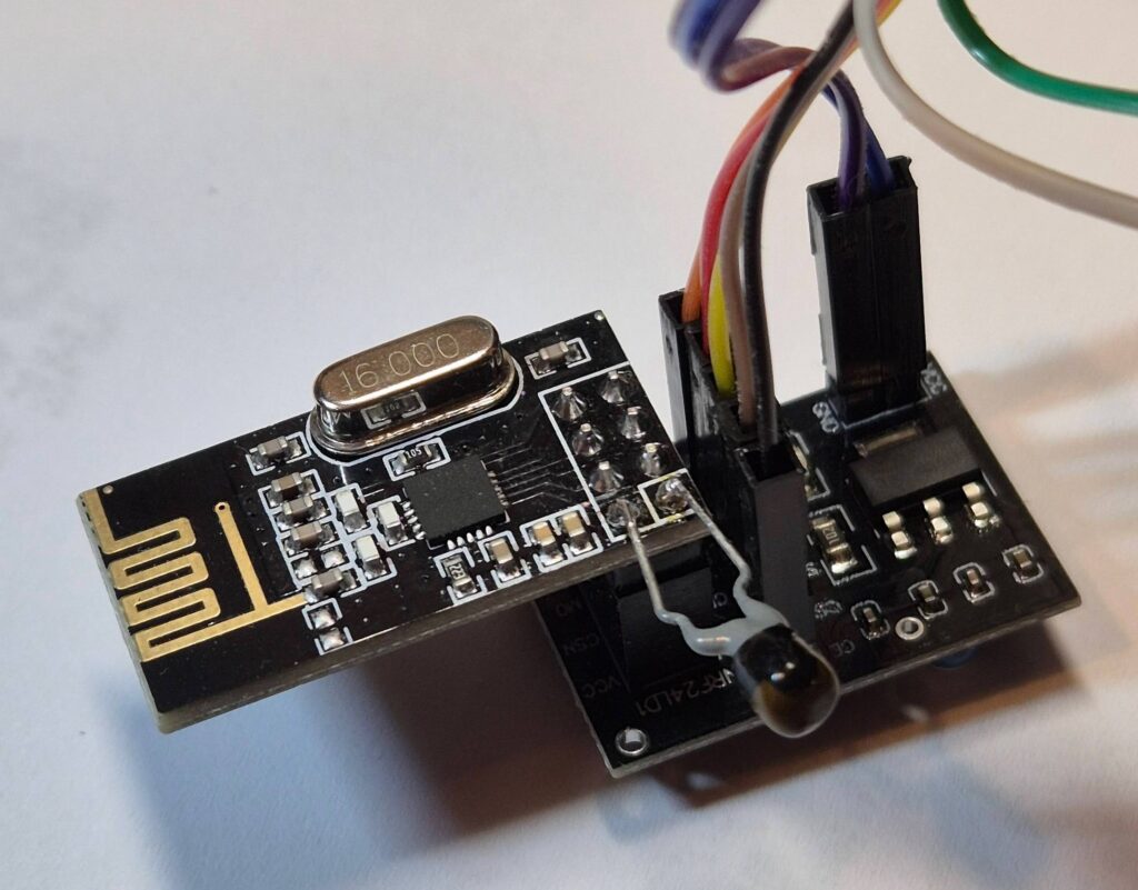
An NRF24L01 module mounted on an adaptor board. The 10uF tantalum
bead capacitor soldered to the power pins is optional
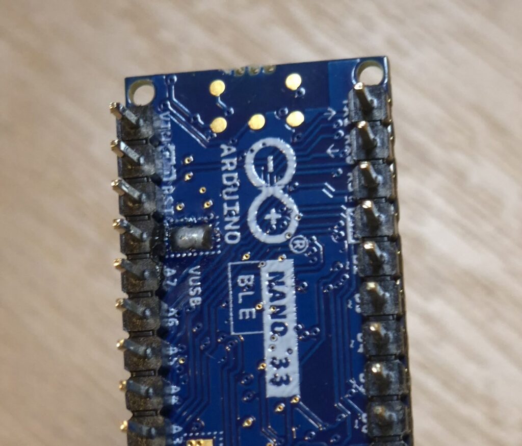
Of course, you will still need a suitable power source for the adaptor board. The two pins on the adaptor board are labelled VCC and GND and you can see them – with a cable plugged in – on the top right of the above photo. They need a supply of between 4.8V and 12V. One option to consider is the VUSB pin on the Nano board, but this will only work if you are using the USB connector to power your Nano and you have put a solder bridge across the relevant two pads on the Nano board. Connect the adaptor’s GND to a GND pin on the Nano and connect the adaptor’s VCC pin to the pin labelled VUSB on the Nano (it’s between A7 and RST). Note: Never connect the Nano’s VUSB pin directly to the VCC pin on the NRF board. It can only be used to power the voltage regulator on the adaptor.
The VUSB pin can be used as a 5V output to another board provided you have bridged the little solder pads inside the dotted rectangle next to the pin (see below). It gets the 5V feed from the USB socket so it won’t work if you are powering your Nano just with the VIN pin. Once activated, make sure you do not allow the 5V from VUSB to touch any of the Nano’s other pins because this would damage the Nano.
Using a buck converter
I had some success using a buck converter to provide the 3.3V supply directly to VCC on the NRF module, but it will depend on what you want to use as the main power source for the Nano. I was fortunate to have a mains powered regulated 5V supply available during my tests. I added an MPM3610 buck converter to this existing 5V power supply so it could be used as a multi-purpose dual output bench power supply. The MPM3610 can deliver more than 1 amp at 3.3V so it is overkill for powering a single NRF board. There must be cheaper alternatives, but I haven’t tested them thoroughly.
The 5V supply was connected to the Nano’s VIN pin and the 3.3V supply – from the buck converter – connects directly to the VCC pin on the NRF module.
This setup gave quite good reliable results. Do make sure the two supplies have a common ground – I suspect that at least one of my NRF modules was destroyed by using an independent 3.3V supply and failing to ensure that ground on both supplies were connected together. When installing the buck converter, I also added a capacitor on the input and another on the output – 4.7uF (only because that’s what was in my cupboard). Tantalum are a good choice because they are good at suppressing high frequency noise which can be a risk with this type of voltage regulator. The capacitors are not shown in the above diagram.
Other power options tried
My tests included a few other power options, mostly using a Li-Ion battery clipped into a cheap battery management board. In theory, it provided regulated 5V and 3V outputs, but I found the NRF radio was very unreliable when powered from this battery-based solution. It only worked okay when the Nano 33 BLE was powered from my laptop PC through its USB socket, leaving the battery-based power supply just powering the NRF. Even then, it would only give reliable results when the 5V battery output was used to power the NRF adaptor and not when I tried to use the 3V output directly into the NRF board itself. During testing, I destroyed two NRF24L01 boards, but wasn’t able to pinpoint the exact cause.
Software options
First, I must acknowledge that others have gone down this path before me and published some fantastically useful material that goes into far greater depth than I would attempt. In particular, there are several posts in the Arduino forum from someone called Robin2 and whose writings provide the foundation for my tests and for the work of many others who wanted to use this radio module.
The first post in a series written by Robin2 can be found here: Simple nRF24L01+ 2.4GHz transceiver demo – Projects / Showcase – Arduino Forum
The posts written by Robin2 are dated 2016 and, even though he has since added a few updates, I didn’t find they addressed all of the problems I was encountering. Furthermore, they describe setting up the NRF24L01 with a 5V UNO Arduino, whereas I was testing it with the 3.3V Nano equipped with the nRF52840 processor.
Test environment
Development work and testing was carried out using the Arduino IDE, version 2.3.4. To test the quality of a radio connection you need two devices – one transmitting and the other receiving. So I used two Nano 33 BLE devices (these use the nRF52840 processor) and each had its own NRF radio module plugged into an adaptor and connected as described above, with power from the Nano’s VUSB pin to the adaptor. Initially, I wanted to test each device on its own to make sure the basics were working.
Sketch development and initial tests
As mentioned earlier, the connection between the Nano microcontroller and the NRF24 radio uses SPI which requires the SPI library, but this is included with every Arduino platform and doesn’t need to be explicitly installed. However, the RF24 library does need to be installed using the standard library management tools – the version used here was 1.4.11 of the RF24 library by TMRh20. You will find there are several example sketches that come with this library and a good one to start with is Examples>RF24>scanner. It allows you to test the radio module on its own and, assuming there are some Wi-Fi networks nearby, you can see which channels are already busy and which look free. Before running this sketch, you might need to set the pin IDs for CE and CSN. I was using pins 7 and 8. Here is a snippet from near the beginning of that example sketch showing how a couple of necessary header files are included and how the DIO pin numbers are initialised:
#include "RF24.h"
#include "printf.h"

//
// Hardware configuration
//

#define CE_PIN 7
#define CSN_PIN 8
// instantiate an object for the nRF24L01 transceiver
RF24 radio(CE_PIN, CSN_PIN);
Also mentioned earlier is the problem of knowing which bit isn’t working when you start running tests. Consequently, you may want to modify the example very slightly to make it write some debug information while it is initialising the radio. Here I show highlighted a few extra lines added to provide more feedback to the serial monitor when the sketch first starts. This is just a snippet from the setup(void) function in that example:
  if (!radio.begin()) {
    Serial.println(F("radio hardware is not responding!!"));
    while (1) {}  // hold in infinite loop
  } else {
    Serial.println("RF24 Radio has started");
  }

  radio.stopConstCarrier();  // in case MCU was reset while radio was emitting carrier wave
  radio.setAutoAck(false);   // Don't acknowledge arbitrary signals
  radio.disableCRC();        // Accept any signal we find
  radio.setAddressWidth(2);  // A reverse engineering tactic (not typically recommended)
  for (uint8_t i = 0; i < 6; ++i) {
    radio.openReadingPipe(i, noiseAddress[i]);
  }

  radio.printPrettyDetails();
With those minor modifications, you should definitely see a message either confirming the radio has started or that the “radio hardware is not responding”. The printPrettyDetails() function simply writes some extra information to the serial monitor confirming the configuration settings. It’s not really necessary, but it is quite reassuring to see it when you first start. You should see something very much like this:
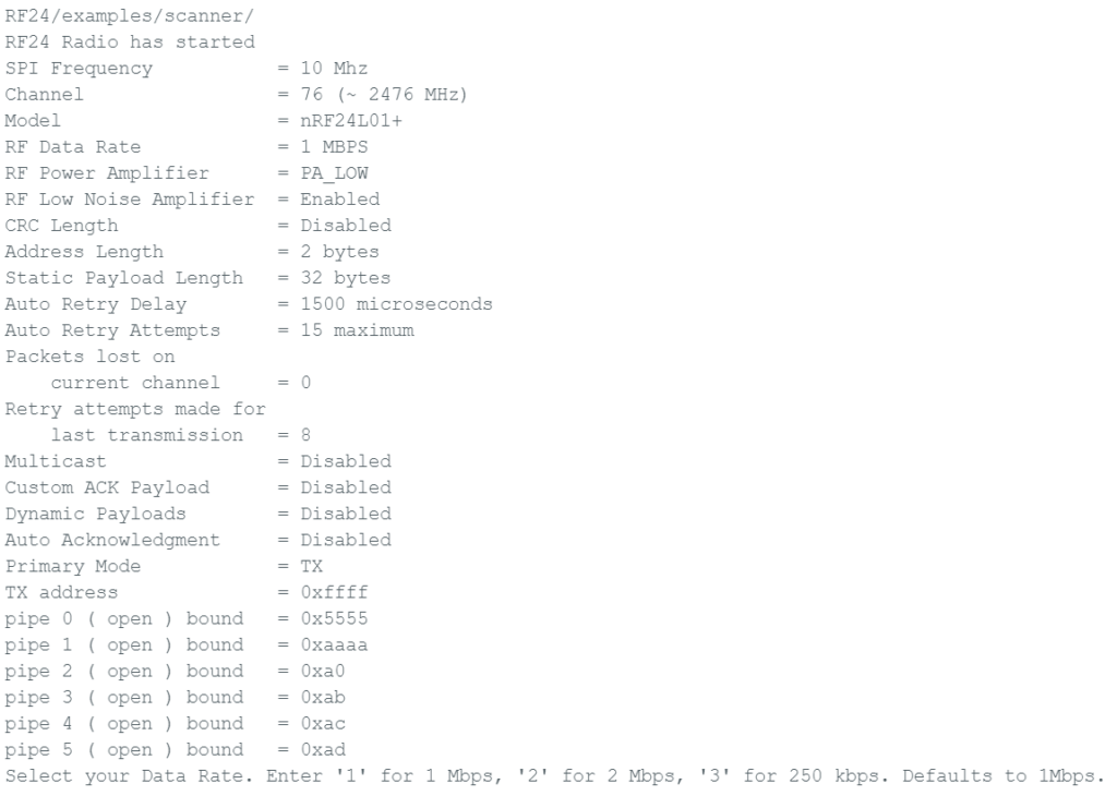
If the radio hardware is not responding, please check all your wiring and the power supply voltages. If you have a number of NRF modules, this might be the time to try a different one. However, if your wiring or power supply is wrong, there’s a chance that you are damaging the NRF module so be very careful not to swap them one after another and thereby destroy all of them. Another approach to debugging this type of problem would be to try a completely different SPI device and make sure it works as expected – assuming you have something suitable available. If you suspect there is a problem with configuration of the SPI bus, consider testing it with a sketch that simply attempts to read register values from the device on the SPI bus. Try Googling for this or try installing the Adafruit BusIO library which I believe includes an example.
To run the scanner sketch as a scanner, enter a negative number (e.g. -2) in the Serial Monitor input box and press return (I had it configured to send both NL and CR). It will probably start out saying that it is sending a carrier wave on channel 0. Just enter the negative number again and press return. This time it should start scanning. Results are shown as a line of dashes and single-digit numbers below the heading block, with one new line added about every 15 seconds. After a while, the monitor should look a bit like this:
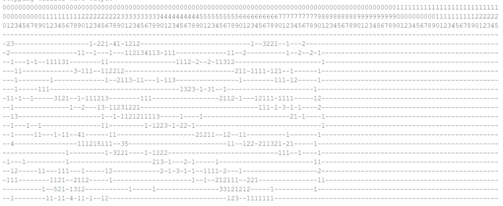
Where I live, there are quite a lot of private houses nearby all using WiFI so my results set looks quite busy. If you tested it in a more remote area, there might be very little traffic.
The results in the picture above show that channels above 80 are clear of traffic. Things are fairly clear around channels 5 to 8 too. Most of the rest has some activity. If this stuff interests you, try comparing with an app on your smartphone such as WiFi Analyser. I only show it as a way to prove your NRF24L01 module is working. If, like me, you want to test two independent devices communicating by radio, then it’s a really good idea to prove that both are working on their own before attempting to send messages from one and receive on the other.
Sketches used to test communication between two devices
For this, my two devices were running different sketches. The sketches described here are just for basic testing, but I wanted to be able to carry out the tests with only one device connected to my laptop while the other one would operate unmonitored and powered from a battery, thus making it totally portable. The idea was to be able to monitor the quality of the radio connection with one device in a fixed location writing info to my PC screen and the other device being portable, allowing me to test reception from different locations around the house or outside.
Both sketches were configured to use channel 86 because scanner results told me it was clear of local WiFi traffic. The fixed location sketch sends a short message every 2 seconds. One character within the message is a single digit number that increments each time a new message is sent, until it goes back to zero after 9. We write this digit to the serial monitor and then either a + or an exclamation mark depending whether it received an acknowledgement. The code looks like this:
#include <SPI.h>
#include <printf.h>
#include <nRF24L01.h>
#include <RF24.h>

RF24 radio(7, 8);

const byte TXaddress[6] = {"00001"};

char txNum = '0';

unsigned long currentMillis;
unsigned long prevMillis = 0;
unsigned long txIntervalMillis = 2000; // send every 2 seconds
unsigned int prcount = 0;

void setup() {
  // put your setup code here, to run once:
  Serial.begin(19200);
  unsigned int to = 1000;
  while (!Serial && --to)
    delay(1);

  Serial.println("SimpleTx Starting - Channel is 86");

  if (!radio.begin()) {
    Serial.println(F("radio hardware is not responding!!"));
    while (1) {}  // hold in infinite loop
  } else {
    Serial.println("RF24 Radio has started");
  }

  radio.setChannel(86);
  radio.setDataRate( RF24_1MBPS );
  radio.setPALevel(RF24_PA_HIGH);
  radio.setRetries(4,8);
  radio.stopListening();
  radio.openWritingPipe(TXaddress);

  radio.printPrettyDetails();     // comment this line out if not wanted
}

void loop() {
  // put your main code here, to run repeatedly:
  currentMillis = millis();
  if (currentMillis - prevMillis >= txIntervalMillis) {
    send();
    prevMillis = currentMillis;
  }
}

void send() {
  bool rslt;

  char textToSend[10] = "Value:   ";
  char txNum = '0';
  txNum += prcount % 10;
  textToSend[8] = txNum;
  rslt = radio.write(&textToSend, sizeof(textToSend));
  Serial.print(txNum);
  if (rslt) {
    Serial.print("+");
  } else {
    Serial.print("!");
  }
  prcount++;
  if (prcount > 70) {
    Serial.println();
    prcount = 1;
  }
}
The portable device was programmed to receive and decode the short message coming from the fixed device. It will automatically acknowledge receipt of the message and this is an important element of the test. If the acknowledgement works, then the fixed sending device shows +. If no acknowledgement is received, the sending device shows ! So only the fixed device needs to write output to a serial monitor, but this shows you if there is 2-way communication and shows how reliable it is. This portable device just needs a battery pack (and USB cable) to power it via the USB port. If both devices are connected to a serial monitor, then you’ll get even more information: it will show if the message is being received at all. Quite often, I found messages were received just fine, but the acknowledgement would not make it back to the sending device.
#include <SPI.h>
#include <printf.h>
#include <nRF24L01.h>
#include <RF24.h>

RF24 radio(7, 8);

const byte RXaddress[6] = {"00001"};
char textReceived[32];
bool newData = false;

void setup() {
  // put your setup code here, to run once:
  Serial.begin(19200);
  unsigned int to = 1000;
  while (!Serial && --to)
    delay(1);

  Serial.println("SimpleRx Starting Channel is 86");
  if (!radio.begin()) {
    Serial.println(F("radio hardware is not responding!!"));
    while (1) {}  // hold in infinite loop
  } else {
    Serial.println("RF24 Radio has started");
  }

  radio.setChannel(86);
  radio.setDataRate( RF24_1MBPS );
  radio.setPALevel(RF24_PA_HIGH);
  radio.startListening();
  radio.openReadingPipe(1, RXaddress);
  radio.startListening();
  radio.printPrettyDetails();     // comment this line out if not wanted
}

void loop() {
  // put your main code here, to run repeatedly:
  getData();
  showData();
}

void getData() {
  while (radio.available()) {
    radio.read(&textReceived, sizeof(textReceived));
    newData = true;
  }
}

void showData() {
  if (newData == true) {
    Serial.print("Data received ");
    Serial.println(textReceived);
    newData = false;
  }
}
What should the output look like?
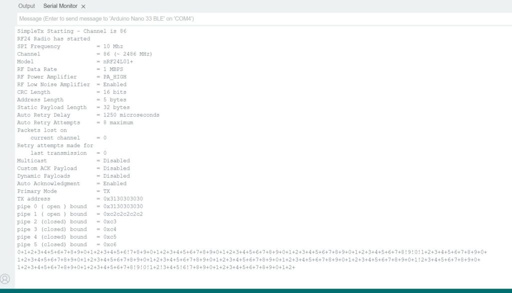
Look closely at the last line and you’ll see that a few of the single digit numbers are followed by ! whereas most of the time they are followed by +.
This shows how most messages are acknowledged okay, but not all. If you find that most, or all, digits are followed by ! then you may have too much distance (or too many walls) between the transmitter and the receiver. I was able to reliably transmit up to about 6m using the above sketches and the version of the NRF24L01 that has an onboard antenna. If your transmitter and receiver are quite close together (say 1m apart) and the acknowledge is failing, then try improving the power supply. In a very recent test, I got less than 1% success when powering the portable device from the USB port of my laptop and about 99% success when I powered it from a power bank.
Conclusions
If you persevere, it is possible to get reliable communication over short distances. No doubt, the versions that allow you to connect a dedicated antenna would transmit over greater distances. You could also turn up the transmit power to MAX rather than HIGH. However, these devices are just too fussy and delicate for my liking. They are absurdly sensitive to qualities in the power supply that are difficult to fathom – sometimes powering from the computer’s USB port would work best and sometimes not. It all came down to trial and error to make them work. I broke half of the radio modules I bought for testing and didn’t even know how. From now on, I’ll be using the RFM69HCW for radio communication.
References
Simple nRF24L01+ 2.4GHz transceiver demo – Projects / Showcase – Arduino Forum
Connecting the Radio | MySensors – Create your own Connected Home Experience
nRF24L01 – How It Works, Arduino Interface, Circuits, Codes (howtomechatronics.com)
nRFBox/nRFBox/scanner.cpp at main · cifertech/nRFBox · GitHub
Leave a Reply