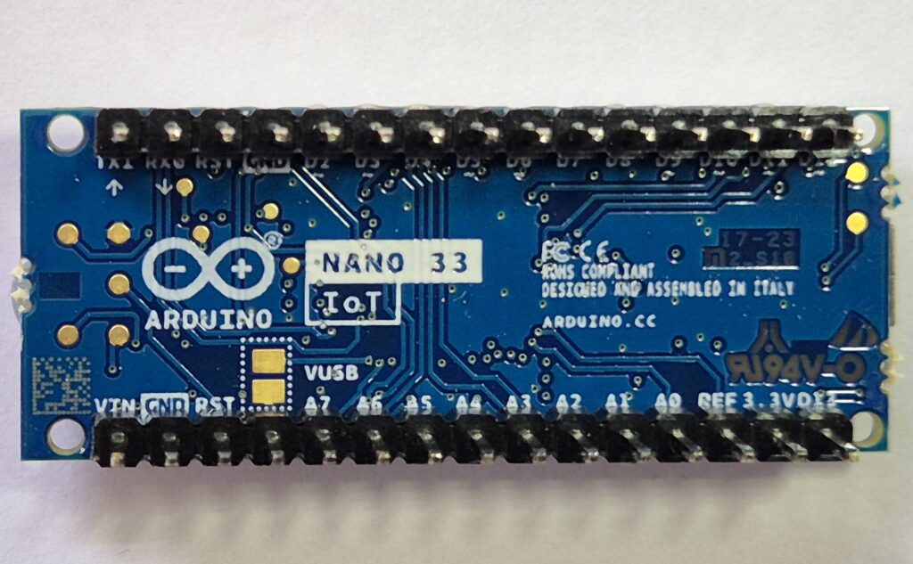
In this article, I will describe my attempts to minimise power demand in the Arduino Nano 33 IoT and select the best combination of batteries to use.
My objective was to build a battery powered environment monitoring station using an Arduino. This might be an outdoor weather station tracking temperature, pressure and humidity or something to track indoor temperatures. Long battery life was a primary concern, but it also had to be compatible with various sensors. I started by looking at board choice and this is discussed in detail in a companion article here.
Finally I moved on to investigate using a solar panel to prolong battery life using the Adafruit BQ25185 battery management module. This is discussed in another article, Nano 33 IoT Testing with Solar Power.
Power options for the Nano 33 IoT
What are the power options for the Nano 33 IoT? These are a bit mixed and, furthermore, the official documentation is terrible. Here’s what I believe to be correct. The options that are deemed acceptable in the official documentation are as follows:
- The VIN pin, using a power supply between 4.5V and 18V
- The USB socket, taking power from the usual 5V pin on this socket
Using either of the above external power options, it is then possible to power peripherals using the 3.3V pin. The documentation fails to clearly state how much current can be drawn from this pin, but schematics and specifications indicate that up to about 500mA should be possible. It certainly looks better than the Nano 33 BLE in this respect. I have used it with the RFM69HCW radio module and not had any problems getting enough power from the 3.3V pin.
But what if you want to power your Nano 33 IoT directly from an external regulated 3.3V supply? Unlike the Nano 33 BLE, this board doesn’t have a track that you can cut to isolate the 3.3V rail from the output of the onboard voltage regulator. I did a lot of searching online for the answer to this question and found I was not alone in wondering whether it is safe to use the 3.3V pin as an input and connect a stable external 3.3V supply to it. For example take a look at this forum thread: How can I power my Arduino Nano 33 IoT? With no option to isolate the rail by cutting a track, you risk damaging the onboard voltage regulator by “backfeeding” it.
I could find no definitive answer, so I just tried it. In fact, I connected the 3.3V output from the Adafruit BQ25185 battery management module directly to the 3.3V pin on my Nano 33 IoT after first disconnecting all other power sources (VIN and the USB). So far, nothing has blown up or gone wrong. If you do this, it’s at your own risk and DO NOT do it while there is any other power source such as a connection to the USB port.
Reducing current drain when power is applied to VIN
For the first set of tests, I used battery packs or a bench power supply connected to the VIN pin. By routing the power through a multimeter, it was easy enough to measure how many milliamps the board was drawing. This allowed me to investigate how changes to the supply voltage and the program’s sleep mode influenced power consumption.
For these tests, the external power source ranged from 5V to about 8.3V. The 5V source was a mains powered bench power supply. All the others simply used battery packs with various batteries arranged in series. Comparisons were made where the software either used the vanilla delay function when pausing between sensor readings or used a low power sleep mode provided by calling an appropriate library function (LowPower or RTCZero). The results looked like this:
| External power source VIN voltage | Vanilla millis delay function (delay) | RTCZero low power library (rtc.standbyMode) | Arduino low power library (LowPower.deepSleep) |
| 5 V from a bench power supply | 30.1 mA | 22.3 mA | 22.3 mA |
| 6.4 V from battery pack A: 4 x 1.5V Alkaline AA batteries | 23.5 mA | 5.3 mA | 5.3 mA |
| 8.0 V from battery pack B: 6 x 1.2V Ni-MH rechargeable AA batteries | 9.5 mA | 3.1 mA | 3.0 mA |
| 8.3 V from battery pack C: 2 x 3.7V Li-Ion 18650 rechargeable batteries | 9.0 mA | 2.9 mA | 2.7 mA |
The table highlights a result that surprised me – higher voltage power packs seem to have a bonus impact on current reduction over and above what you’d expect. I can only conclude that the onboard voltage regulator needs a decent difference between its input and output voltages. When that difference is small, it is relatively inefficient. So, it is more efficient with higher input voltages. With a 5V supply, the saving made using a low power sleep mode is useful, but a bigger improvement is possible if you increase the supply voltage on the VIN pin to at least 7 or 8 volts. Of course, doing both gives the best result.
How do we interpret the results in terms of power drain
One important fact that the table above fails to show is that the power drawn by the board is not just related to the current. Power is the product of voltage and current, so we really need another table to show how the power demand changes according to voltage. I prefer to show this as a graph:
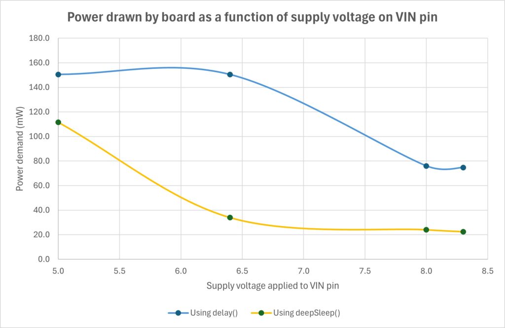
The smooth lines connecting data points on the graph are just an approximation using the smooth line regression built into Excel, but they make it easier to see what the graph has to say than the data points alone. It confirms that supply voltages above about 7V significantly reduce the power demand, especially when combined with the low power library (it doesn’t really matter which library, so I just plotted one on the graph). It also emphasises the benefit of using a low power sleep mode rather than just using the delay(millis) function between sensor readings.
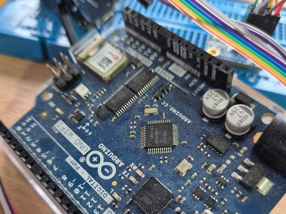
The onboard power LED
The Nano 33 IoT has an LED on either side of the USB port as shown here:
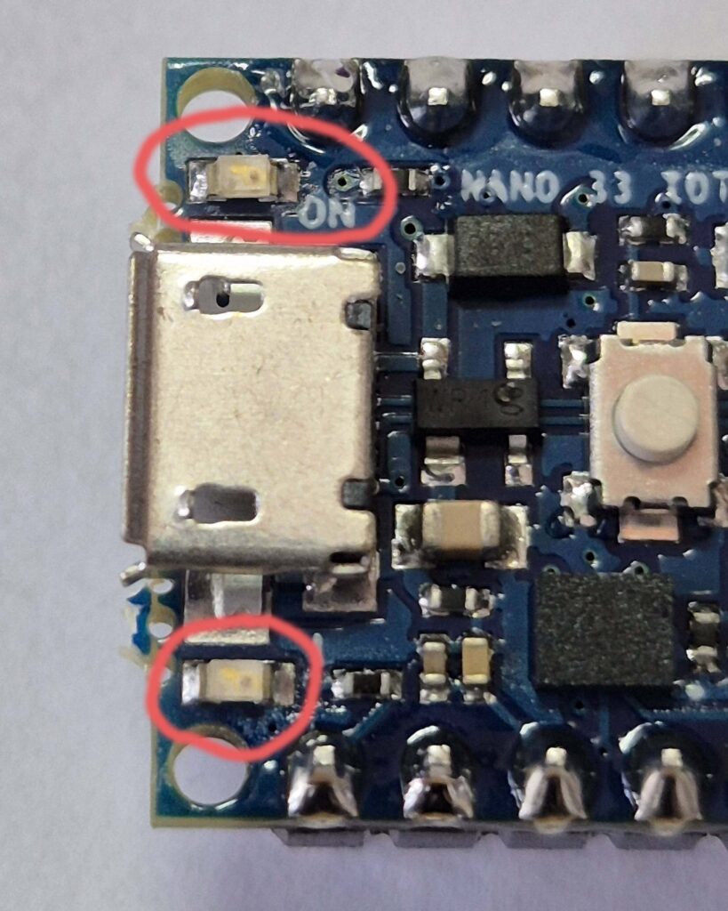
The LED labelled ON, at the top of the picture, comes on whenever the board is powered. This LED is responsible for approaching 2mA of current drain on the input to VIN when using an 8.3V supply. There is no software switch, jumper or track you can cut to disable this LED. I resorted to removing it with a hot soldering iron (with a very fine tip) and a tiny jewellers screw driver to lever it off. My software can still momentarily flash the other LED on from time to time to show that the board is active, but I considered the improvement in battery life was worth the risk of damaging the board.
Comparison when using an external voltage regulator
As mentioned at the start of this article, instead of using the VIN pin, you may want to connect a stable external 3.3V supply. Although it is not recommended and could even cause damage to your Arduino board, I have been powering a Nano 33 IoT this way for some time and had no problems so far.
The board used for this test was configured as a working sensor node. It was connected to a temperature sensor and a radio module, but the measurements of current were made between sensor readings while the board was essentially idle. Furthermore, this board had no power LED – it had been removed as described above. The tests were a little bit different in so far as I didn’t try the RTCZero method and only used the sleep function rather than the deepSleep function from Arduino low power library.
| External power source to 3.3V pin | Vanilla millis delay function (delay) | Arduino low power library (LowPower.sleep) |
| 3.3 V from a bench power supply | 18.9 mA | 6.9 mA |
About battery choices and recharging
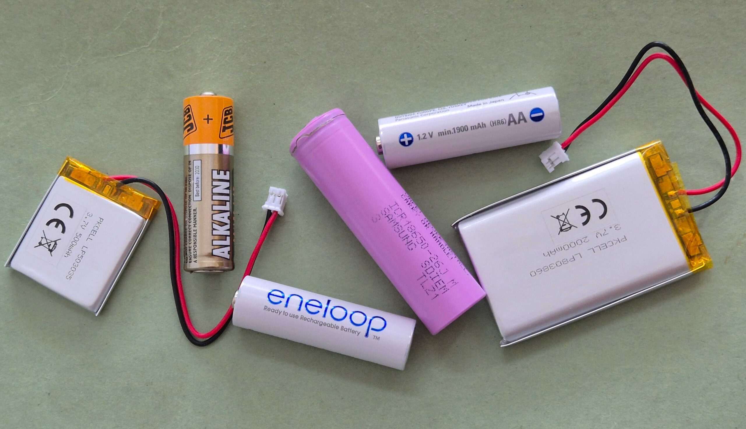
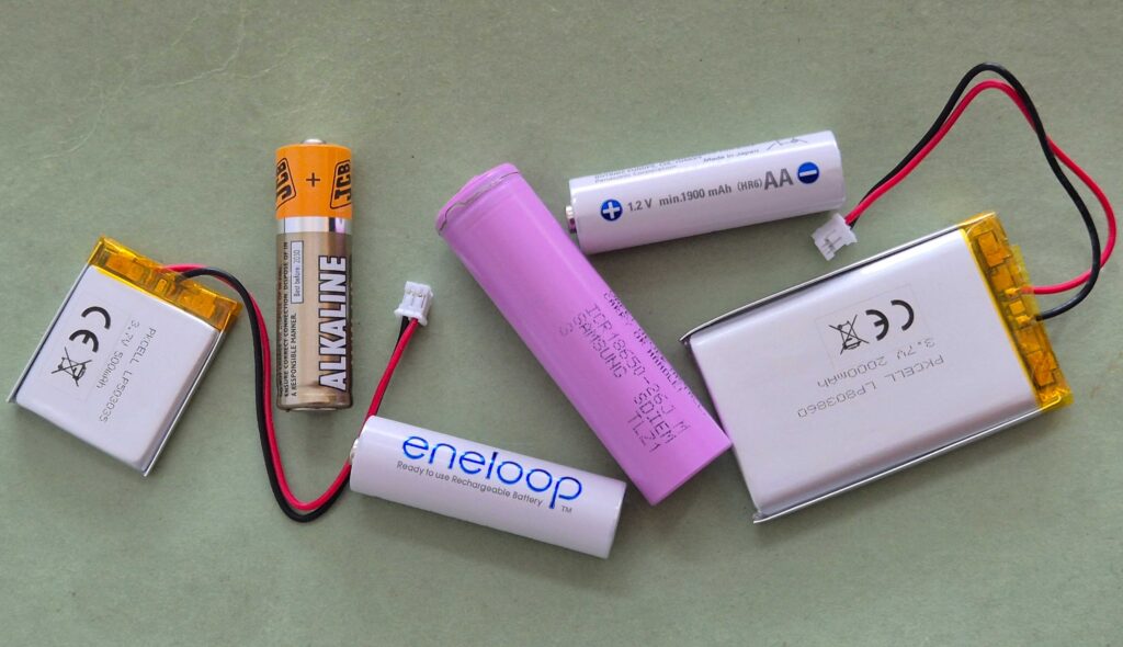
While all the above observations and tests of battery voltage, current and power drain are interesting, you have to pay due regard to the battery choice and battery configuration. If you achieve higher voltages simply by connecting more battery cells in series, then you will also be increasing the energy capacity of the power pack (and making it bulkier and heavier).
Battery chemistries
Different battery chemistries may have relative strengths and weaknesses – for example, how quickly they discharge when stored with no load, their tolerance to heat or cold, their lifespan, “energy density” and even their safety. This is a vast topic and there are books written on it. If you scale it up and look at how rechargeable batteries are used in electric vehicles and building services, there is a whole industry specialising in the topic. Thus, choosing the right battery combination is really quite a complex subject and I’m not going to go there beyond a few basics.
If you are concerned about fire safety, non-rechargeable alkaline batteries are pretty good. When it comes to rechargeable batteries, NiMH and LiFePO4 are safer than Li-Ion. However, NiMH tend not to hold their charge as well as Li-Ion and have a significantly lower energy density. LiFePO4 are difficult to source in smaller packages such as AA or 18650 and they operate at a slightly lower voltage than Li-Ion which greatly reduces the choices available for battery management and charge controllers. The lower voltage range is also annoyingly tricky to match with the 3.3V power requirement of the Nano 33 microcontrollers – being too low when the battery is discharged and too high when fully charged – so you have to use an up-down buck booster. These are quite rare, but DFRobot make one that accepts 2.5V to 15V input and delivers regulated 3.3V up to 600 mA.
There are several variants under the broad heading of Lithium-Ion and they have different strengths and weaknesses. Some would not be appropriate for powering small devices like Arduinos, but it’s good to be aware of the options. There’s plenty of online information explaining the relative merits of different chemistries. Here are a couple of examples:
The Six Major Types of Lithium-ion Batteries: A Visual Comparison
https://www.ufinebattery.com/blog/nimh-vs-li-ion-15-essential-facts-compared
Recharging options
So far, I have discussed directly connected battery packs or a bench power supply. With the exception of the off-the-shelf power banks, the battery packs using rechargeable batteries cannot be recharged while in use. It would be necessary to disconnect the battery pack, remove the batteries and put them in a suitable charger. This is because the Nano 33 IoT doesn’t have any built-in battery management components.
Off-the-shelf Power Banks
Off-the-shelf power banks can be used to power the Nano 33 IoT, although note the caveats below. They would normally be connected to the USB socket on the Nano. These mostly use Li-Ion batteries and they will usually tolerate being charged on one socket while, at the same time, powering an external device via another socket. They are not the cheapest solution, but when you consider the convenience and the fact that they have integrated battery management they can be pretty good value. A couple of precautionary points based on my experience testing with one make of power bank:
- It would shut down after a short time because the power drawn by the Nano 33 was so small it thought it was disconnected
- It had 4 LED’s that would stay on while it was powering anything and no option to kill them – such a waste
Conclusions and follow up
A relatively high voltage is needed on VIN to keep the power drain low, but most cells in everyday use will only supply between 1.2V and about 3.7V. This pushes you in the direction of using two or more cells in series, which means a heavier and bulkier solution. It also reduces your options for charging on the fly because most of the cheap battery management modules are designed for a single cell. There are some Chinese modules available on eBay that appear to work with two cells in series, but I haven’t tested any of these.
My next step was testing with a single Li-Ion battery, an Adafruit battery management module and a small solar panel. That article is here.
After that, I may get one of the Chinese 2S modules to see how well it performs, but I’m toying with the idea of buying a battery management chip and building my own BMS. Or reviewing the full range of solar power BMS modules available to see which look most promising.
As for low power mode and deep sleep functions, I only tested the simplest implementation – calling just one function in a standard Low Power library. The results were good, but if you want to get really long battery life, there’s a whole lot more can be done and there are online articles and forum posts explaining the lengths to which some people go to get the sleep mode power drain down to micro-amps rather than milli-amps. The Gammon Forum thread included in the references below is a good starting point.
My tests only looked at power drain in sleep mode because most of the time my environment monitoring stations will be sleeping while they wait for the next sensor readings to be made. The frequency of sensor readings and the frequency of transmission back to the base node will also have a strong bearing on battery life. Radio or Wi-Fi transmissions will use a lot of power so keep them short and infrequent – they don’t have to be done as often as sensor readings if you’re not too bothered about being able to see real-time data and your coding skills are up to it. De-activate the radio (or Wi-Fi) when it is not being used. The same goes for the sensors.
If you found this article useful, please click the Like button at the end or leave a comment.
References
The Arduino Guide to Low Power Design | Arduino Documentation
Gammon Forum : Electronics : Microprocessors : Power saving techniques for microprocessors
Arduino Sleep Modes and How to use them to Save the Power
Powering Alternatives for Arduino Boards | Arduino Documentation
Some interesting forum threads
Nano 33 IOT power consumption > 22mA in sleep – Nano Family / Nano 33 IoT – Arduino Forum
Achieving lowest power – Nano Family / Nano 33 BLE – Arduino Forum
https://forum.arduino.cc/t/how-can-i-power-my-arduino-nano-33-iot/1357443/14
Leave a Reply