My objective was to build a battery powered environment monitoring station using an Arduino. It might be an outdoor weather station tracking temperature, pressure and humidity or something to track indoor temperatures. Long battery life was a primary concern. In a previous article, I investigated how to minimise power demand and select the best combination of batteries (see my earlier article Nano 33 IoT Testing Battery Options and Low Power Mode). The final step, described here, introduces a small solar panel in combination with a single Li-Po battery and the Adafruit BQ25185 battery management module – the version with a built-in 3.3V buck converter.
I wanted to see how useful a solar panel is for prolonging battery life. Ideally, you would want the solar-battery combination to work well enough that there is no longer any need to change or manually recharge the batteries. My experience is based on testing with a very small solar panel which I felt sure must be undersized, but the lessons learnt are interesting so I thought I’d share them here.
Choice of Battery Management Module
I chose the Adafruit BQ25185 module because the Texas Instruments battery management chip on which it is based, the BQ25185, includes over-voltage protection and current limiting. The chip is designed to accept solar power as an input and the implementation is uncomplicated. I also liked the fact that Adafruit have included an integral 3.3V 1 Amp buck converter – I thought this might be very useful although I initially had some questions about how to connect it to the Nano 33 IoT. Another positive point is that Adafruit generally provide easy-to-digest documentation. Price and availability also influenced my choice.
The issue of connecting the 3.3V output so it could power the Nano 33 IoT is discussed in detail in my earlier article, so I won’t bother to repeat it all here. Suffice to say, I connected it to the 3.3V pin and if you do the same please note that this is not an officially documented solution and is not without risk.
Choice of Solar Panel
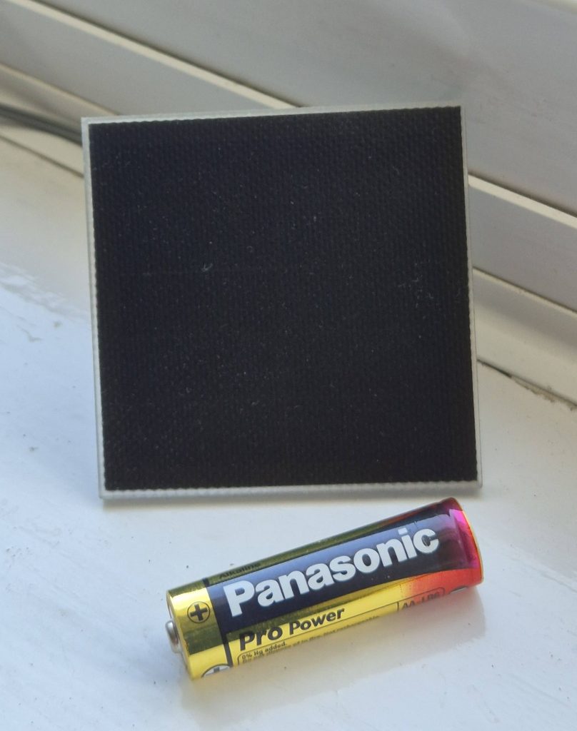
Adafruit recommends using a solar panel with a supply voltage between 5V and 7V. They say it is safe to go well above 7V, but there is little or no benefit as the extra energy will be lost as heat. I decided to look for a small 5V or 6V panel that wouldn’t be too expensive – there seemed no point spending a lot on the solar panel for what was essentially an experimental proof of concept project. The primary object was to get some experience and learn how the batteries, BMS, solar panels and loads interact and work together. The panels available from my usual supplier – the Pi Hut – included some small ETFE panels from Voltaic and there was one in stock rated at 0.7W and 5V costing just over £10. That seemed like a reasonable price and Voltaic looked like a reputable make so I ordered one. The online description said the voltage could go up to about 6V and 120 mA peak making it a good fit for the recommendations from Adafruit for something between 5V and 7V.
I expected the small 0.7W panel to be a bit undersized for powering my project, but the only way to know for sure would be through testing.
Test environment
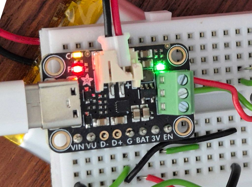
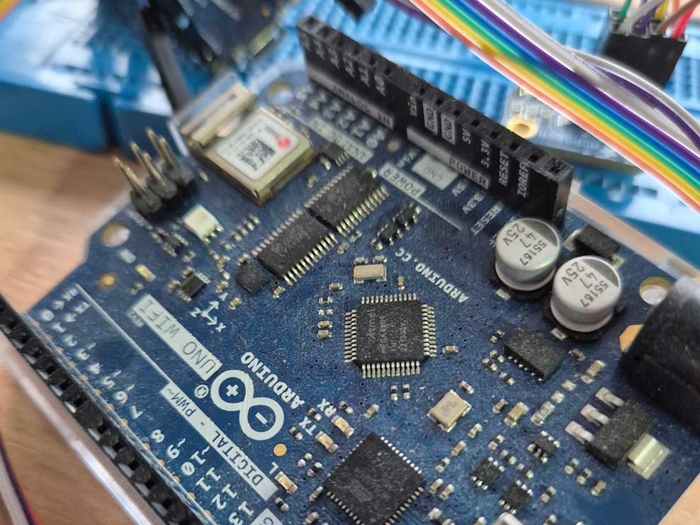
A 2000 mAh LiPo battery was connected to the battery socket on the BQ25185. You will see on the photos that the socket is broken – this happened when I was struggling to unplug a battery. The fitting was very tight; I was a little heavy handed; it broke. On the positive side, I now have no problem unplugging batteries since breaking the socket and the fit is still firm.
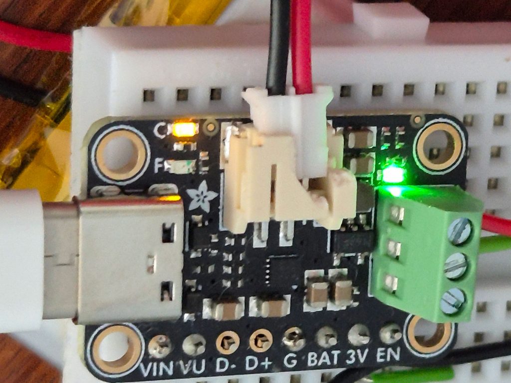
Let’s explain what this photo shows. It’s hard to see, but there’s a LiPo battery underneath the white breadboard. The battery is connected by the small plug inserted in the (broken) JST 2-pin battery socket at the top of the Adafruit module – red and black lead. The green terminal block with three screw terminals to the right of the module provides the stabilised 3.3V output that was used to power the Nano IoT – red and green wires can just be seen to the right of the block in the top two screw terminals. The third screw terminal provides a stabilised 4.5V output, but this wasn’t used.
There are 8 pins along the bottom of the module, but you cannot see what has been connected to these. The solar panel connects to the VIN pin (positive) and G (ground). The BAT pin was used to send the battery voltage to an analogue input pin on the Nano IoT via a voltage divider (two resistors in series) thereby allowing the Nano to monitor the battery voltage. I didn’t use the pins labelled VU, D-, D+ or EN. The one labelled 3V simply duplicates the topmost terminal on the 3-way screw terminal block.
Coming in at the left of the picture is a cable connected to the module’s USB-C socket. This is being used to charge the battery and to power the Arduino Nano from an external power source. External charging via the USB socket, as shown in the photo, should in fact only be necessary when the solar panel is disconnected (or there is too little sunlight) and the LiPo battery is seriously discharged and getting near empty.
There are three status indicator LEDs. The green one just above the screw terminal block is on whenever there is a 3.3V output – pretty much all the time unless you disconnect battery, solar panel and USB. The LED labelled F to the left of the JST battery socket is not lit. It comes on (red) when there is a fault. More on that later. The one just above it labelled C is orange and it shows if the battery is being charged. It can be quite dimly lit sometimes if there is no USB connection and barely enough sunlight to meet the load and charge the battery.
LiPo battery voltages
To get a reliable objective measure of the battery voltage, I used a multimeter. This gives good accuracy, but is not very convenient. I therefore configured the Nano to continuously monitor the battery voltage. The BAT pin on the module can be used for this. Here is the circuit I used:
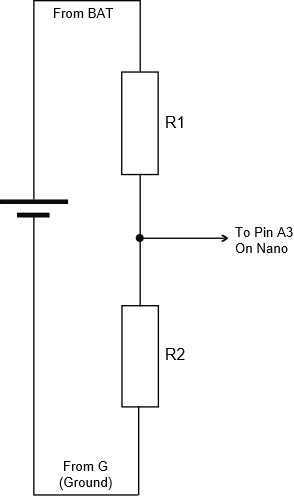
The resistors were selected partly based on calculation, then by what I already had in the cupboard and finally by testing. The values finally arrived at were: R1 is 120 kΩ and R2 is 68 kΩ. As an example, when the battery voltage measured 4.03V on my multimeter, it read 1.49V between R1 and R2. The expected range for battery voltage would be approximately 4.2V when fully charged and something like 3.3V when it is close to empty. The code used on the Nano to turn the reading from pin A3 into a value I could report and log looks like this:
float readBatteryLevel() {
  float measuredvbat = analogRead(VBATPIN);
  measuredvbat *= 2.66;    // adjust for resistor chain potential divider
  measuredvbat *= 3.3;  // Multiply by 3.3V, our reference voltage
  measuredvbat /= 1024; // convert to voltage
  Serial.print("VBat: " ); Serial.println(measuredvbat);
  return(measuredvbat);
}
Of course, the program has to define a value for VBATPIN before the function is defined. I was using pin A3 so it was simply set to A3.
Charging control using the BQ25185
The first tests were done in the summer when there were many hours of daylight and the sun was quite strong. The small Voltaic solar panel was placed behind a south facing window and angled for optimum exposure to the midday sun. Even in these ideal conditions on a clear sunny day, the current delivered was small and so the rate of charging was slow. I was starting with an almost empty battery and anticipated the small solar panel would need a long time as it would only charge the battery slowly. However, in my tests something was stopping the charging after about 6 hours. At the point where it stopped, the red “Fail” led would come on even though the battery voltage was still well below the magic 4.2V that represents a fully charged condition.
I did some research and found that the BQ25185 chip has a built-in safety timer. Could this be the culprit? The data sheet states that the time limit should be 12 hours, but in my tests something was stopping the charging much sooner. As stated above the red “Fail” led came on. The Texas Instruments chip has two status pins which can be used to determine why charging stopped – one drives the red lamp labelled “F” and the other one drives the orange lamp labelled “C”. However, this only allows you to differentiate between four possible situations. In this particular case, both lamps were lit. The data sheet says this indicates a non-recoverable fault including “pin short” or “safety timer expired”. The latter seemed like the most likely because the experiment was repeatable and the red lamp always came on after the same fixed amount of time.
The fault condition is cleared as soon as the voltage from the solar panel drops to zero. This happens naturally every night when it gets dark, but you can also manually reset the status of the battery management chip by momentarily disconnecting the solar panel or simply turning the panel face down for a few seconds. I would guess that a brief cycling of the enable pin would also restart things from scratch – unfortunately the enable pin presented on the Adafruit board is for the voltage regulator and not for the main BMS chip.
During longer periods of sunny weather and after a few days, the battery would reach the fully charged condition and the BMS would simply switch off charging to protect the battery. When this happens, the charging LED (C) switches off. The red fault LED (F) does not come on. This is how the BMS chip should end charging if everything goes to plan. The manufacturer’s notes indicate that, in this situation, solar energy may still be used to power downstream equipment if the battery is fully charged and solar power is still available.
On one or two occasions the battery reached a fully charged state (in less than 6 hours) AND the red fault light came on. It was difficult to see why this happened, but my guess is that the rate of charge from the small solar panel – in weak or diffuse sunlight – was so slow that it somehow evaded the usual monitoring process for detection of full charge. Anyway, I thought it was reassuring that the chip seemed able to correctly protect the battery from overcharging under a range of different conditions.
Battery discharge rate with and without solar
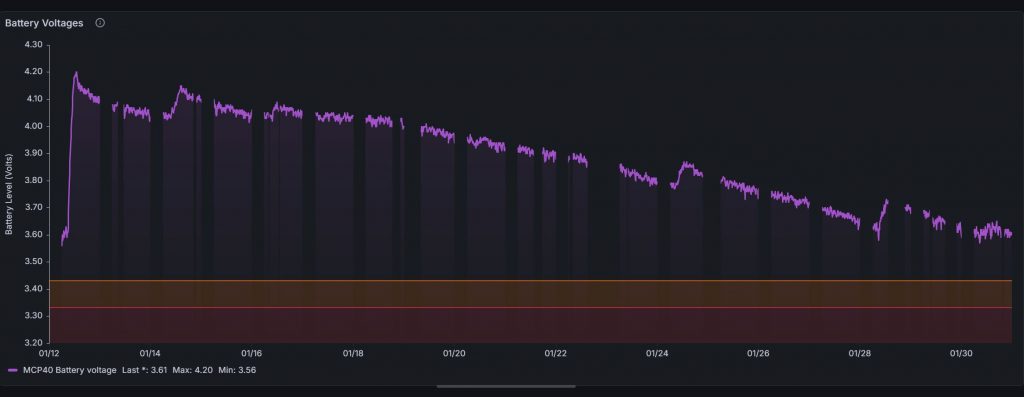
The combination of Adafruit BQ25185, Nano IoT (with RFM69 radio), small Voltaic solar panel and 2000 mAh LiPo battery has now been on test through a summer and a winter. I have been able to record performance through a prolonged dull autumn gloom which lasted over 2 weeks, through sunless winter days and also through sunny spells in all the seasons. Let’s start with how the battery discharged when there was just about no sun at all for a couple of weeks in October – the weather forecasters called it anticyclonic gloom.
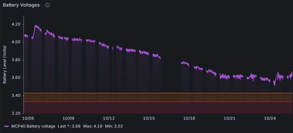
The graph has lots of breaks because my Wi-Fi switches off overnight and also the code needs a bit more work to make it reconnect when there is a problem, but the rate of discharge of the battery is clear to see. The 2000mAh battery was good for over 2 weeks with almost no help from the solar panel.
Now let’s see what happens at the other extreme when there are plenty of daylight hours and the weather is generally sunny.
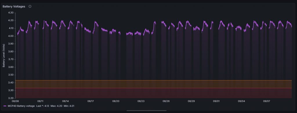
The graph shows how almost every day the battery gets recharged back to its maximum (4.2V) after which the battery slowly discharges for the rest of the day. The voltage only drops by about 0.15V before the next morning when the sun falls on the solar panel and the battery is recharged again. Drilling down to individual days, shows how on some days it could take until mid-afternoon to reach full charge while on other sunnier days the fully charged state is reached by 10:15 a.m.
There is a period of several days in the middle where it must have been cloudy, but even during this period there was some solar power contribution because the battery voltage never drops below 4V over the entire 32 day period.
In fairly sunny autumnal conditions, the small solar panel could still just about hold its own over long periods. The following graph shows battery voltage for a period of 16 days in late November/early December:
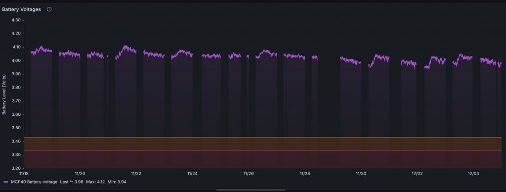
However, in the depths of the UK winter when we often see very little sun and the daylight hours are significantly reduced, the little solar panel was simply unable to make up for the power used by the Nano IoT and the net result was a gradual decline in battery voltage.
Conclusions
On the Voltaic 0.7W solar panel
This panel was good value and seems to be well made. The panel itself looks tough and should have no problem exposed to the weather, but the terminals on the back of the panel are simply two solder pads so you would have to improvise to make the reverse side weatherproof. Its small size could be an advantage if space is limited, but for an unattended Arduino project (i.e. one that runs all the time without needing the battery to be changed or recharged) this little panel is very unlikely to be enough. From a cursory look at readily available solar panels, the prices seem to quickly jump to at least £25 for a 2W panel and over £75 for a 10W panel.
On the Adafruit BQ25185 with 3.3V buck converter
All in all, the Adafruit BQ25185 module works quite well and did a good job of distributing solar power safely and sensibly. I felt fairly confident that it wasn’t going to overcharge the LiPo battery. However, it was frustrating to discover that the Texas Instruments chip has a built-in safety timer, there seems to be no way to adjust its duration and the pre-set duration is only 6 hours. More recently, I have noticed that the Adafruit web pages for modules using TI’s BQ25185 chip include a notice about the 6 hour time limit. This is the notice for the module that doesn’t have a 3.3V buck converter:

What a pity it is that Adafruit do not present the chip enable (CE) pin on any of the pads on the module with the buck converter. Instead, the EN pin that is presented is only for the buck converter and not for the main BMS chip. Easy access to the CE pin would allow you to rig up a reset driven by the Arduino, thereby restarting the safety timer. If you get the Adafruit module that has no buck converter it does have a pad for CE that can be used.
The 6 hour charging limitation is a serious flaw – you need to be able to harvest all the energy available on sunny days to give you more chance of making it through the dull and cloudy days. For a serious project I would certainly look for alternative BMS modules that either allow greater access to the control pins of the main BMS chip or perhaps use a chip that can be programmed. Alternative modules include:
- The DFRobot “Sunflower” Solar Power Manager 5V which uses the CN3165 chip. However, be careful that your solar panel will not exceed the input voltage.
- The DFRobot “Sunflower” Solar Power Manager with part number DFR0535. It accepts solar panels with a voltage between 7V and 30V as input and it has multiple outputs at different voltages including 3.3V and 5V. Unfortunately, it is quite expensive.
- Adafruit Universal USB / DC / Solar Lithium Ion/Polymer charger. Uses the BQ24074 chip. It accepts 5V to 10V input.
On the use of solar power for Arduino projects
What did I conclude more generally about the use of solar panels to power your Arduino projects? The 2000mAh battery had just enough capacity to run my temperature monitor project for 2 weeks even when there was no sun. The project had been optimised to draw very low power between readings – even to the point where I had removed the onboard power LED. It used a Nano IoT that reads the temperature every 10 minutes and transmits the reading back to a base station by radio.
It’s important to use a battery management system to manage the routing of solar power and stabilise the power output to the Arduino board. In particular, you do not want the rechargeable battery to be overcharged and you need protection from short circuits or other unforeseen problems that might draw too much current from the battery and risk a fire.
In the next iteration of this project, I will use a solar panel that can deliver at least 2W, probably 3W. The British weather is simply not reliable enough so you need to be able to make full use of the sun’s power when it is there and even be able to harvest a bit of solar energy on overcast days. I would also avoid BMS modules that use the BQ25185 chip for the reasons mentioned above. Make sure the voltage rating of the solar panel is matched to the input voltage range of the BMS – many small panels are 5V or 6V, but those are not the only options. Big solar panels will use higher voltages than this. Think about location and weather resistance too – you will probably want the solar panel to be outside, facing south. However, rechargeable batteries must not be allowed to get too hot – this not only means keeping them out of direct sunlight but also avoid locations and enclosures that might get cooked on a hot sunny day.
Leave a Reply