I have been designing and building a weather station to put in my garden at home. It will be a one-off project so I don’t need to compromise on cost – instead, I want something that will be reliable and, if anything, slightly over-engineered. This particularly applies to the power source – it has to be exclusively solar powered and there must be minimal risk of battery fire as it will be located close to a wooden shed. I also wanted it to work reliably through a gloomy English winter. Here we look at all aspects of the battery choice including finding a suitable solar charger battery management module. A companion article will focus on battery monitoring using an Adafruit INA219 module.
Based on earlier experience with a very small 0.7W solar panel, this time I started with a 6V 2W solar panel. The higher output should provide enough current even when it’s cloudy. To allow continuous operation through the sunless winter months it needs a high capacity battery, but my concerns about fire risk meant I didn’t want to use typical Li-Ion batteries based on Nickel-Manganese-Cobalt chemistries and providing a nominal 3.7V (full charge voltage is 4.2V). Instead I opted for a cell based on Lithium Iron Phosphate – LiFePO4 or LFP for short. These have a lower nominal voltage of 3.2V (full charge voltage is 3.65V). In the next section, I’ll explain this decision in more detail.
Why choose LiFePO4?
Comparing LFP with NMC
LiFePO4 batteries are rapidly gaining popularity because they offer several advantages over Nickel-Manganese-Cobalt (NMC) solutions. They are safer because they have better thermal stability and tolerance to high temperatures making them less likely to catch fire when under duress. They also offer a more sustainable solution than NMC because iron is readily available while metals like Nickel and Cobalt are much scarcer and often mined in ways that raise concerns about environmental destruction and labour exploitation. However, NMC batteries have a higher energy density than LFP so historically they were the preferred choice where size and weight are really important – e.g. electric cars and portable or wearable devices. LiFePO4 batteries were, and still are, widely used for storing solar energy for off-grid activities like caravans and camping and also for so called “Power-Wall” solutions in eco-friendly houses. In these situations, size and weight are less critical.
Apart from being safer and better environmentally, LiFePO4 chemistry has another advantage over NMC – a premium LFP battery can be expected to last at least 3 times longer than NMC batteries under comparable charge/discharge cycling. This means you could expect a useful life of over 7 years for a battery that gets daily charge/discharge cycles.
In recent years, partly for the reasons mentioned above and partly because they are cheaper, LiFePO4 batteries have started to displace NMC as the preferred option for electric vehicles. Many of the popular Chinese EV’s sold in the UK today have LiFePO4 batteries.
Why LiFePO4 cells are not a drop-in replacement for NMC
Each LFP cell has a nominal voltage of just 3.2V and a fully charged voltage of 3.65V. This compares with 3.7V/4.2V for NMC cells. So you need to be careful to choose a charger or battery management solution that is designed to work with LFP. Furthermore, LFP batteries have a lower storage capacity than NMC in the same size of package. For my project, this pushed me towards using a 26650 sized battery rather than the more common 18650.
Getting to grips with LiFePO4 batteries
The choice of battery led me down an interesting path. Firstly, I found there was very little choice when it comes to the purchase of single cell LiFePO4 batteries. There were plenty of 12V or 24V combination units designed for caravans, camping and other “off-grid” activities, but very few in the form of 18650 or similar. Next, it seemed that most of the solar charge solutions compatible with Arduino are aimed more at 3.7V cells, not 3.2V cells. Finally, I discovered that the voltage discharge curve for LiFePO4 batteries makes it difficult to get a reliable indication of the State of Charge (SOC) of the battery based only on the voltage across its terminals.
Sourcing a modest sized LiFePO4 single cell battery
It is possible to get LiFePO4 cells in smaller package sizes including 14500, 18650 and 26650. However, they are primarily offered as replacement parts for repair projects and there is very little choice. I wanted the battery to have a capacity of at least 3000mAh and the 14500 cells offered too little. Even the 18650’s were borderline so I decided to go for the 26650 size and ordered two from RS. That plan failed because RS told me they could only sell them to trade accounts. I was just about to give up when I found a solution on eBay: a seller there was offering replacements for emergency lighting that were in a 26650 package, had 3800mAh capacity and came with wires pre-connected to the terminals. The wires were terminated with a chunky 2-pin plug for connection to the emergency light, but I carefully snipped the plug off and used a 2 channel screw terminal choc-block connector instead. Considering it was a lot cheaper than the RS batteries and didn’t need a special battery holder, I was happy. Look out for the UK seller called “electricalbargainhunt” if you want the same, but if you snip the plug off make sure the wires can’t short circuit.
Selecting a solar charger module for LiFePO4
Once again, the choices available for Arduino hobbyists to get solar chargers that will work with LiFePO4 (3.2V/3.65V) were not as good as the choices available for Li-Ion based on NMC chemistries (3.7V/4.2V). While I was not super happy with the 6 hour charging limit that is baked into the Adafruit BQ25185 modules, their basic module is actually highly configurable because (a) they provide several cuttable tracks and solder bridge-pads for options like nominal battery voltage and maximum charge current and (b) several very useful pins from the BQ25185 chip are presented as solder pads along the edge of the module board.
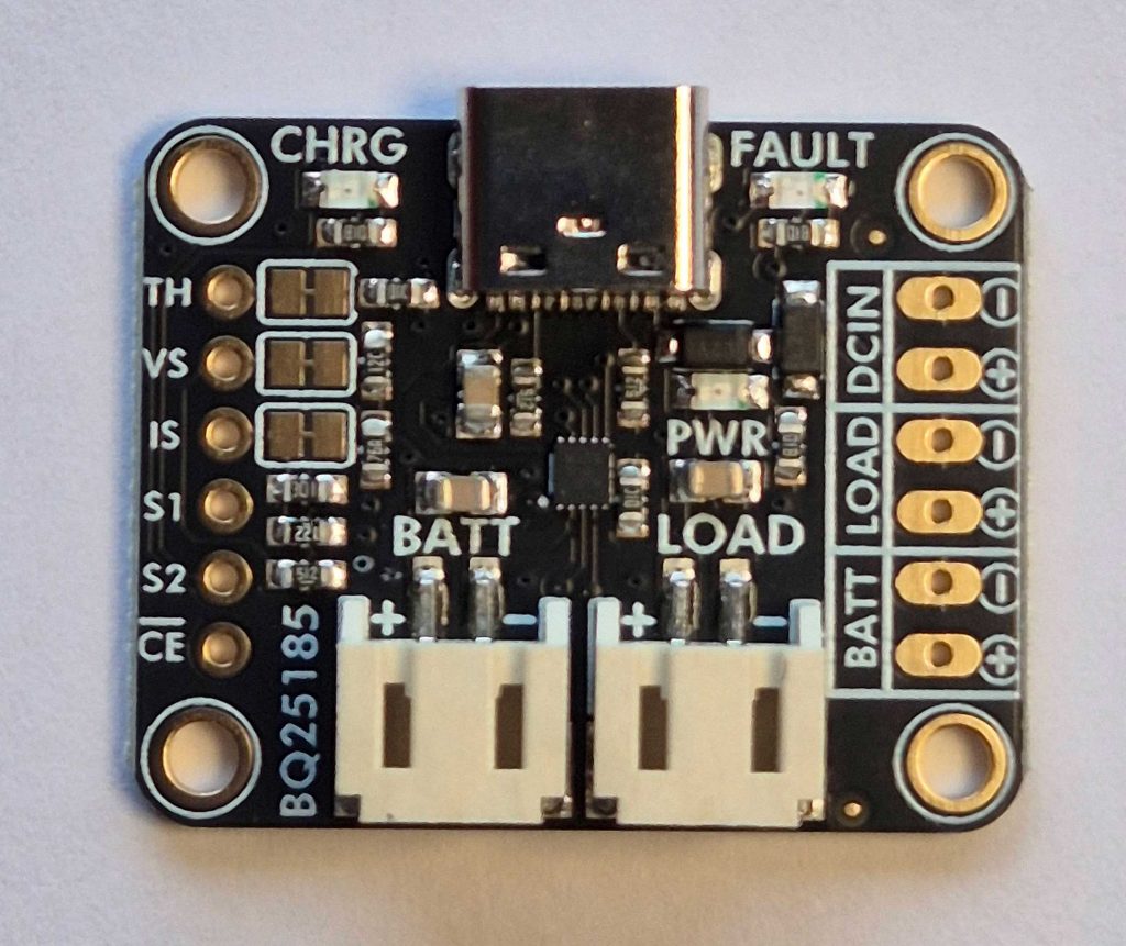
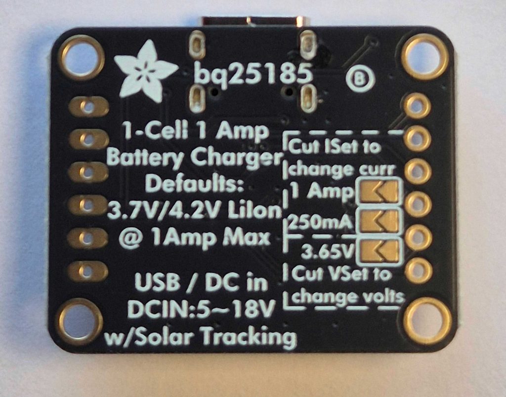
With access to those pins it should be possible to monitor the charging status using S1 and S2, to send a reset signal if you want to extend beyond the 6 hour limit and even to disable battery charging at any time using the chip enable pin (CE). The TH pad allows connection of a thermistor which can be used to monitor battery temperature and automatically disable charging should the battery temperature go outside the safe charging range. All-in-all, this module seemed to offer everything I needed in a small package at a reasonable cost.
How to track the state of charge of the battery
This is potentially quite challenging. The battery voltage can almost reach 3.65V when fully charged, but it only needs a tiny current drain for a few hours to make that voltage drop down below 3.35V. This graph illustrates the initial discharge curve for my LiFePO4 cell shortly after it had reached a fully charged state. I turned off the solar panel at 14:00 because, prior to that, the BQ25185 was allowing small bursts of recharging or was allowing solar energy to directly power the Arduino device. After 14:00, the load (which is pretty trivial at around 10mA) is exclusively supplied from the battery. You can see how the voltage falls rapidly in the first 4 hours and then levels out at about 3.32V:
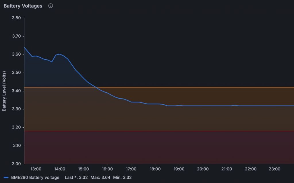
The first time I saw this, I cursed the battery supplier for selling me a dud! But no, there was actually nothing wrong with the battery. It’s just the behaviour of these LiFePO4 batteries. Most of the time while discharging, the voltage will sit between 3.20V and 3.35V. That means you only have a tiny voltage range to use for estimating the state of charge of the battery – frankly, not enough to give you an accurate reliable metric. In the example shown in the graph above, the battery would easily last more than 10 days.
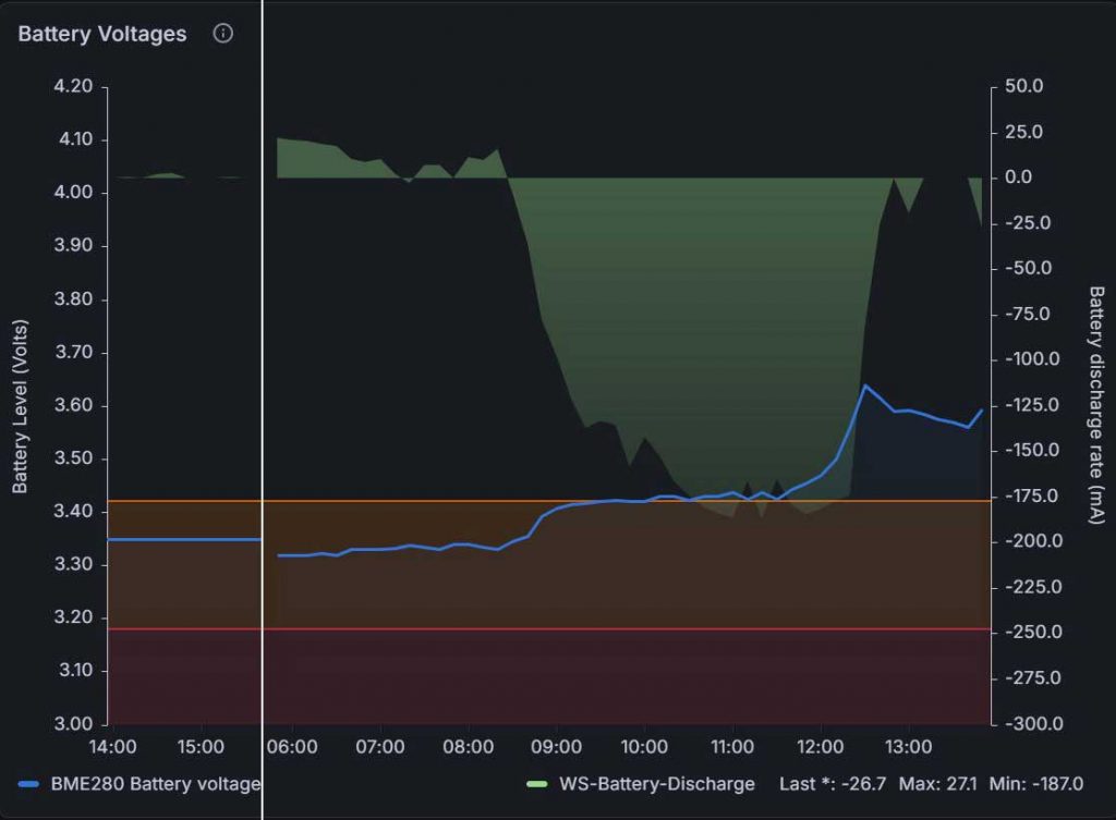
I started to investigate the idea of monitoring the current flows in and out of the battery because that might allow me to estimate the state of charge provided I had an accurate measure of net current flow since the last known state. In the end, the clearest marker for state is when the battery is either fully charged or fully discharged. My line of thinking was, it should be possible to detect when the battery reaches full charge or when it is empty and after that I can keep a track of how much charge has gone in or come out. Somewhat ambitious, but it might at least end up allowing me to estimate the SOC with a little more accuracy than using voltage alone. An AI chatbot suggested using the INA219 chip for this job and I then discovered that Adafruit make a module based on this chip. So, I decided to add another module to my project. At the time of writing, the design for a so-called Coulomb Counting ‘State Of Charge’ monitor is still mostly just in my head, but it is now possible to see what is happening in some detail. The following image shows a plot of discharge current (right-hand scale; negative values are where it is charging) and battery voltage (left-hand scale; blue line) on a sunny morning when the battery is already quite near being fully charged.
For a more detailed review of how I used the Adafruit INA219 module to measure and record current drain and battery recharging, you will have to wait for the companion article that is still being written.
Getting the right regulated voltage to power a Nano 33
As can be seen from the voltage plots above, the LiFePO4 battery voltage can easily drop close to – or even below – 3.25V. Now the Arduino Nano 33 requires a regulated 3.3V supply so it is important to choose a voltage regulator that can handle the full range of input voltages and deliver 3.3V. The specification for the regulated output from the BQ25185 is somewhat vague and only guarantees that the voltage will not exceed 4.5V. It offers no guarantees about how low the voltage might drop. I therefore assumed the lower voltage from the BQ25185 would be directly linked to the battery voltage. This meant I needed a voltage regulator that could accept input voltages as low as 3.0V and up to at least 4.5V. There were very few modules available to hobbyists that could meet the specification. I chose the DFRobot DC-DC mini Auto Boost Buck Power Module which can operate with an input voltage of 2.5V-15V and delivers up to 600mA of regulated 3.3V output.
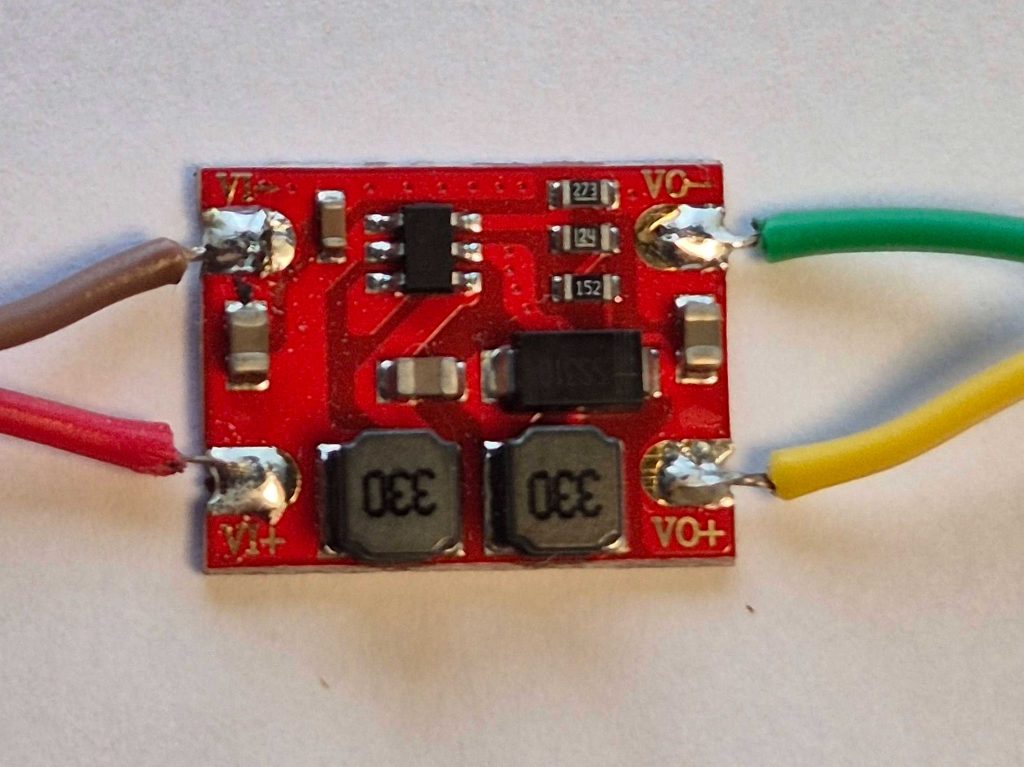
The only problem I found with this DFRobot regulator was its small size and complete lack of fixing holes. I solved the problem of how to fix it in place by soldering a couple of pins to each terminal and then soldering the other end of the pin to a small piece of stripboard. I wanted to get the electronic components into a standard plastic enclosure that measures 150mm x 80mm x 50mm (that’s 6″ x 3.25″ x 2″ for our transatlantic friends). I decided to mount the battery on the outside because it should stay cooler that way and it also meant I could get everything else into this fairly small box. At this point, I was trying to fit the following components into (or onto) my box while leaving enough space for the Arduino Nano and an RFM69HCW radio module:
- 26650 LiFePO4 battery
- Battery connector board with choc-block connector, fuse and potential divider for analogue battery voltage monitoring
- Adafruit BQ25185 solar charging module
- Adafruit INA219 current detection module
- DFRobot DC-DC voltage regulator mounted on stripboard and with two rows of connector pins (one per power rail)
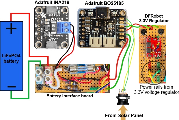
Here is a block diagram showing how power interconnections were made between the above components. Connections for signals and I2C are not shown in this diagram:
…and this is what the battery related end of the box looks like with the lid removed:
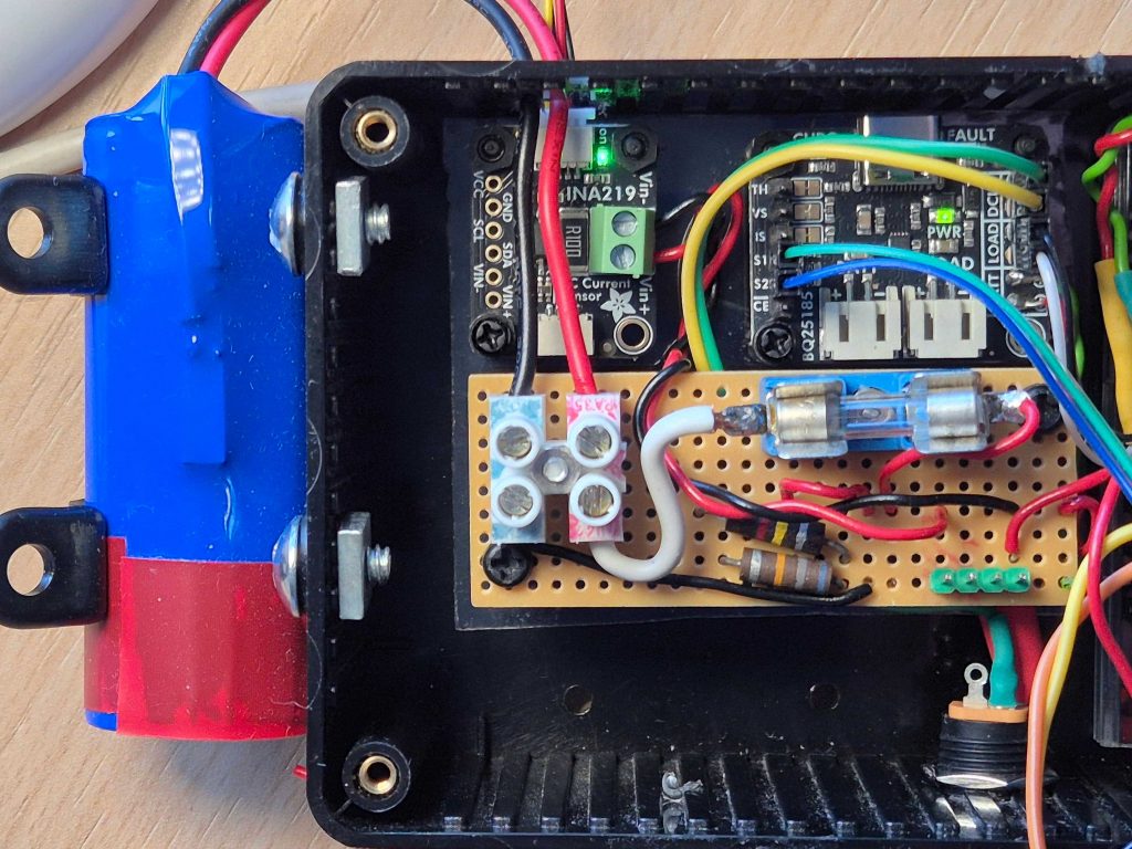
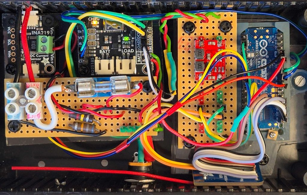
The battery is on the outside, held loosely in place with two P clips. Inside the box, there is a battery connector board constructed using a small piece of stripboard. It has a fuse, which doubles up as a power switch during development, and also has two resistors in a potential divider arrangement to allow connection to an analogue pin on the Arduino Nano 33. This can be used for crude battery voltage monitoring, but for more accurate measurement of battery voltage I use an Adafruit INA219 module which can be seen on the left above the battery connector board. Above right is the Adafruit BQ25185 solar charger module and at the bottom right of the photo you can see a socket which accepts the 5.5mm/2.1mm barrel plug that terminates (via an adapter cable) the connection from the 2W Voltaic solar panel. The DFRobot voltage regulator is just out-of-shot in the above photo but it can be clearly seen in this one:
Conclusions
This project has thrown up some interesting challenges and it is still in development. I’m happy with the LiFePO4 battery choice although issues about measuring and tracking the State Of Charge are still to be resolved. The INA219 module provides some interesting options for monitoring battery charge and discharge current as well as voltage – more about this in the companion article – as well as providing convenient connection options with its two STEMMA QT sockets. By connecting S1 and S2 on the Adafruit BQ25185 module to two DIO pins on the Arduino, it is easy to interrogate the status of the charger control chip. If I want to overcome the annoying 6 hour charging limitation of the BQ25185, then I have the option to connect the CE pin to another DIO pin on my Nano. The DFRobot voltage regulator has worked perfectly. Watch this space for updates.
I’d love to hear your comments or if you just want to click the like button below it is always good to get some feedback. The companion article describing how I used the INA219 and added greater control over the battery charging process will follow in due course.

Leave a Reply